Calculating the Tessellation Level of a Patch
Before a frame is rendered each patch is checked for its necessary tessellation level. It's easy to see from Figure 2 that the error of each patch increases as the number of vertices is reduced. In a pre-processing step, for each level the position of the vertex with the largest error (the one which has the largest distance to the corresponding correct position, later on called "maxerror vertex") is determined and saved together with the correct position.
When determining the level at which to render, all saved "maxerror vertices" are projected into the scene and the resulting errors calculated. Finally the level with the largest error below an application defined error bound is chosen. In order to create a specific level's geometry only the "necessary" vertices are written into the buffers. For example to create level 0 all vertices are used. Level 1 leaves out every second vertex reducing the triangle count by a quarter. Level 2 uses only every fourth vertex and so on
Connecting Patches
If two neighboring patches with different tessellation levels were simply rendered one next to the other, gaps would occur (imagine drawing any of the patches in Figure 2 next to any other). Another problem are t-vertices, which occur when a vertex is positioned on the edge of an other triangle. Because of rounding errors, that vertex will not be exactly on the edge of the neighboring triangle and small gaps only a few pixels in size can become visible. Even worse, when moving the camera these gaps can emerge and disappear every frame which leads to a very annoying flickering effect.
To solve both problems it is obvious that each patch must know its neighbors' tessellation levels. To do so, all tessellation levels are calculated first without creating the resulting geometry and then each patch is informed about its neighbors' levels. After that each patch updates its geometry as necessary. Geometry updating has to be done only if the inner level or any of the neighbors' levels changed. To close gaps and prevent t-vertices between patches a border of "adapting triangles" is created which connects the differently sized triangles (see Figure 3). It is obvious that only one of two neighboring patches has to adapt to the other. As we will see later on in the section "Geomorphing", it is necessary for the patch with the finer tessellation level (having more geometry) to adapt.
 |
| Figure 3a: T-vertices at the border of two patches |
 |
| Figure 3b: T-vertices removed |
Figure 3a shows the typical case where T-vertices occur. In Figure 3b those "adapting triangles" at the left side of the right patch are created to avoid T-vertices. Although these triangles look like being a good candidate for being created by using triangle fans, they are also implemented using strips, since fans cannot be combined into bigger fans as can be achieved with strips.
Materials
Until now our terrain has no shading or materials yet. Applying dynamic light by using surface normals would be the easiest way to go, but would result in strange effects when patches switched tessellation levels. The reduction of vertices goes hand in hand with the loss of equal number of normals. When a normal is removed the resulting diffuse color value is removed too. The user notices such changes very easily - especially if the removed normal produced a color value which was very different from its neighboring color values.
The solution to this problem is easy and well known in today's computer graphics community. Instead of doing real time lighting we can use a pre-calculated lightmap which is by its nature more resistant to vertex removal than per-vertex lighting. Besides solving our tessellation problem, it provides us with the possibility to pre-calculate shadows into the lightmap. The disadvantage of using lightmaps is that the light's position is now fixed to the position that was used during the lightmap's generation.
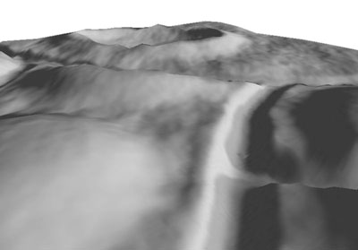
In order to apply a lightmap (see Figure 4) we need to add texture coordinates to the vertices. Since there is only one lightmap which is used for the whole terrain, it simply spans the texture coordinates from (0,0) to (1,1).
 |
|
 |
| Figure 4a: Lit terrain |
|
Figure 4b: Same terrain with wireframe overlay |
Now that the terrain's mesh is set up and shaded, it's time to apply some materials. In contrast to the lightmap we need far more detail for materials such as grass, mud or stone to look good. The texture won't be large enough to cover the complete landscape and look good, regardless of how high the resolution of a texture might be. For example if we stretch one texture of grass over a complete terrain one wouldn't even recognize the grass. One way to overcome this problem is to repeat material textures.
To achieve this we scale and wrap the texture so that it is repeated over the terrain. Setting a texture matrix we can use the same texture coordinates for the materials as for the lightmap. As we will see later this one set of (never changing) texture coordinates together with some texture matrices is sufficient for an arbitrary number of materials (each one having its own scaling factor and/or rotation) and even for moving faked cloud shadows (see below).
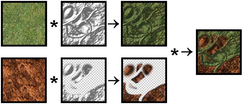
To combine a material with the lightmap two texture stages are set up using modulation (component wise multiplication). The result is written into the graphics buffer. In order to use more than one material, each material is combined with a different lightmap containing a different alpha channel. Although this would allow each material to use different color values for the lightmap too, in practice this makes hardly any sense. This results in one render pass per material which is alpha blended into the frame buffer. As we will see later a lot of fillrate can be saved if not every patch uses every material - which is the usual case (see section Optimization). Figure 5 shows how two materials are combined with lightmaps and then blended using an alpha map. (For better visualization the materials' textures are not repeated in Figure 5)
 |
| Figure 5: Combining two render passes |
In the top row of Figure 5 the base material is combined with the base lightmap. Since there is nothing to be drawn before this pass, no alphamap is needed. In the bottom row the second pass is combined with another lightmap. This time there is an alpha channel (invisible parts are drawn with checker boxes). The resulting image is finally alpha-blended to the first pass (right image in Figure 5).
It is important to note that this method allows each material pass to use a free scaling (repeating) factor for the color values which results in highly detailed materials while the lightmap does not need to be repeated since lighting values do not need as much detail. Only two texture stages are used at once, which allows combining an arbitrary number of passes. Most applications will not need more than three or four materials.
After all materials have been rendered, another pass can be drawn in order to simulate cloud shadows. Again we can repeat the shadows in order to get more detailed looking shadows. As we are already using a texture matrix to do scaling, we can animate the clouds easily by applying velocity to the matrix's translation values. The effect is that the clouds' shadows move along the surface which makes the whole scene looking far more realistic and "alive".

Geo-morphing
|