Camera Class Tutorial
Step 1: Planning
That's right we're not jumping right into code but I promise we will eventually. Before we start programming our camera class we should figure out what sort of stuff we want it to do. When I started writing this class I came up with a list something like this...
* Transformations based on our global coordinate system
* Transformations based on our camera's local coordinate system
* Ability to travel along a spline
* Ability to look at and follow targets
In this article I will be discussing the second, and fourth items in the list.
One thing I need to say right now is that I haven't researched camera classes or even written one before. I simply thought about what I wanted to do and then coded it. Next thing I should mention is that almost all of the transformations in our camera class are going to be based on axes (axes is the plural form of axis, not the weapon) that are defined by vectors. The default orientations for the axes would be as follows:
X Axis = (1.0, 0.0, 0.0)
Y Axis = (0.0, 1.0, 0.0)
Z Axis = (0.0, 0.0, 1.0)
Here we see that the default x axes would point in the direction 1.0, 0.0, 0.0 which is one unit to the right (or left depending on how you want to look at it), zero units up and zero units forward. If you're not following me just keep reading and maybe it will come to you. Our camera will have several different modes that all affect how it will be transformed (rotated, translated). First we will have our default mode where all of our transformations are based on the default axes. Another mode will actually rotate the axes with the camera while also taking into account the previous orientation of the axes. Understand?
Hold out your hand straight in front of you with your palm pointing down and your fingers pointing straight in front of you. Now rotate your hand 90 degrees so that your palm and the back of your hand are pointing left and right. Now if we were using the first mode I described and we wanted to translate the hand upwards it would move up (up being towards the ceiling above you). In the second mode I described the hand would still move up, but up would be left or right (depending on the sign of the translation, +/-). This happens because when we rotated our hand 90 degrees the axes rotated with our hand. That means that up would still be defined as the top of your hand. Therefore when we move up we would actually be moving left or right relative to our default axes. Following me so far? If not try to keep reading and things should become more clear.
Here are some example pictures of what I'm trying to explain. Hopefully they'll help a little bit.
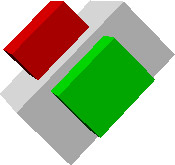
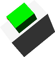
These two pictures show a camera. The red block signifies up relative to the camera and the green block represents forward for the camera. These pictures try to show what happens when we use the second mode I described for the transformations. As you can see in the first picture the camera has been rotated 45 degrees around the forward axis (which was 0.0, 0.0, 1.0). Now take a look at the second picture and you'll see what I mean about the rotations being based on previous rotations. Notice how in the second picture the camera was rotated based on it's local axes. This is the effect that we are going to try to achieve. It is a lot easier to understand if you can simply load up a scene and start navigating around. I may release a little demo that will let you move around in a scene and try out this effect.
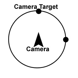
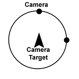
The next two modes affect what is rotated around what. Sound strange? I'll try to clarify. We want to have our default mode where the camera's target (forward vector) will rotate. This changes which way the camera is pointing. The other mode is an orbit mode, where the camera's position rotates around a point. Here are some examples...
Well, now that we have an idea of what we're doing in the next section we'll start exploring the formulas involved in achieving these effects.
Step 2: Exploring Formulas
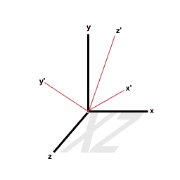
When I first started this camera class I had no idea how I was going to achieve these effects. I started flipping through a mathematics handbook and came across a formula that I thought did what I wanted. I should note that there are probably many ways to get the results we are looking for and mine may not be the best. However it works and it doesn't seem to be slow. Here is a diagram showing what the formula allows us to do.
![]()
And here are the formulas that describe what's going on:
x' = m1x + n1y + l1z
y' = m2x + n2y + l2z
z' = m3x + n3y + l3z
The description from the book is as follows, "where the origins of the xyz and x'y'z' systems are the same and m1, n1, l1; m2, n2, l2; m3, n3, l3 are the direction cosines of the x', y', z' axes relative to the x, y, z-axes respectively".
Don't worry if you don't understand that description because we'll actually be using a watered down version of those formulas. Lets step back a minute and remember what we're trying to do. We want one mode where the camera is transformed based on the default axes positions, and one where the axes rotate with the camera. This formula will let us do both. If you look at the formula description you'll see it mentions directional cosines represented by the l, m, and n variables. These are the keys to our rotations. Here is a diagram showing what they are.
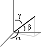
Think of the dark line shown as an axis that we are rotating. Here are the formulas for l, m, and n which were shown in the above equation. Note that the small a symbol is Alpha, the symbol looking like a b is Beta, and the one that looks like a y is Gamma.
m = cos Beta
n = cos Gamma
l = cos Alpha
Where Alpha, Beta, Gamma are the angles which our line (or new axes) makes with the positive x, y, z-axes respectively. Now take a look at the diagram showing directional cosines again. In the diagram rotations on each axis are happening all at once. In our camera class we won't do it this way. Instead we will have three separate methods, one for rotating around the x, one for the y, and one for the z (rotateX(), rotateY(), rotateZ()). This will let us simplify our equations. Lets say we rotate around the y-axis, Gamma should always be 90 degrees. If we rotate around the x-axis, Beta should always be 90 degrees, and if we rotate around the z-axis Alpha will always be 90 degrees. Here is an example showing a rotation around the y-axis. Notice Gamma is 90 degrees.
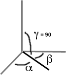
Ok, now we know that we can get at least one angle for each one of our equations. What about the other two? Well if we are rotating around the y-axis (the diagram above) we see that we still need Alpha and Beta. For the x-axis Beta will be the amount the camera is to be rotated, so it will be supplied as a parameter. Now we just need to find Alpha. Take a look at the diagram again. Notice that the x and z-axis are 90 degrees apart. That must mean that to find Alpha all we have to do is take 90 degrees and add the amount we are rotating around the y axis. Lets do a little example assuming that the user wants to rotate 45 degrees around the y-axis.
Gamma = 90 degrees (the new x, and z-axes will still form a 90 degree angle with the y-axis)
Beta = 45 degrees (angle supplied by the user as a parameter)
Alpha = 90 - 45 = 45 degrees
It's that simple. We now know all the angles we need to figure out the new x-axis. We can then take these angles and plug them into our equation to find our new axes! Here's how we do it. Since we were rotating 45 degrees around our y-axis the z and x-axes will change. This means we need to calculate the x, y, and z positions for both the z and x-axes for a total of six calculations. Remember that m = cos Beta, and n = cos Gamma, l = cos Alpha.
x'.x = m1x.x + n1y.x + l1z.x
x'.x = cos(45)(1) + cos(90)(0) + cos(45)(0)
x'.x = (0.7071)(1) + 0 + 0
x'.x = 0.7071
x'.y = m1x.y + n1y.y + l1z.y
x'.y = cos(45)(0) + cos(90)(1) + cos(45)(0)
x'.y = (0.7071)(0) + (0)(1) + (0.7071)(0)
x'.y = 0
x'.z = m1x.z + n1y.z + l1z.z
x'.z = cos(45)(0) + cos(90)(0) + cos(45)(1)
x'.z = (0.7071)(0) + 0 + (0.7071)(1)
x'.z = 0.7071
As you can see in this example we calculate the new vector for the x-axis. We took into account the current position of the axes which were 1, 0, 0 for the x-axis, 0, 1, 0 for the y-axis, and 0, 0, 1 for the z-axis. They could have been something else but for simplicity sake we just used the default. Our new x vector is 0.7071, 0, 0.7071. Our y vector will stay the same since we're rotating around it. The only thing left to find is the z-axis. First we need to figure out the values of Alpha, Beta and Gamma. We know that Gamma will still be 90 degrees. Alpha will be 45 degrees because that's how much we're rotating and Beta will be 90 + 45 = 135 degrees.
z'.x = m3x.x + n3y.x + l3z.x
z'.x = cos(135)(1) + cos(90)(0) + cos(45)(0)
z'.x = (-0.7071)(1) + 0 + 0
z'.x = -0.7071
z'.y = m3x.y + n3y.y + l3z.y
z'.y = cos(135)(0) + cos(90)(1) + cos(45)(0)
z'.y = (-0.7071)(0) + (0)(1) + (0.7071)(0)
z'.y = 0
z'.z = m3x.z + n3y.z + l3z.z
z'.z = cos(135)(0) + cos(90)(0) + cos(45)(1)
z'.z = (-0.7071)(0) + 0 + (0.7071)(1)
z'.z = 0.7071
Now we have all of our new axes' vectors. Their new vectors are as follows:
X Axis = (0.7071, 0.0, 0.7071)
Y Axis = (0.0, 1.0, 0.0)
Z Axis = (-0.7071, 0.0, 0.7071)
Step 3: Optimizations
Optimizations before code? Yes, it will make the coding process so much simpler because we can cut our equations down to size. Take a look at our calculations above and you'll notice that when we rotate around the y-axis our Gamma angle is always 90 degrees. The cosine of 90 degrees is always 0. That means that we don't even have to include our Gamma angle in our equation when we rotate around the y-axis. Here are our new formulas that rotate the x and z-axes around the y-axis.
x' = m1x + l1z
z' = m3x + l3z
Isn't that a lot simpler? For rotating around the x-axis Beta always remains the same (90 degrees). Once again since the cosine of 90 is zero we don't need to include it. So our equations for rotating around the x-axis would be:
y' = n2y + l2z
z' = n3y + l3z
And for our z-axis:
x' = m1x + n1y
y' = m2x + n2y
As you can see this makes our calculations simpler and faster. Now on to the code!
Step 4: Implementation
Yes you finally get to look at some code. But before we jump right in we need to decide on some variables. What kind of information do we need to keep track of? I made a little list.
* A target to look at (our z-axis vector)
* The camera's position
* The camera's up vector (y-axis vector)
* The camera's right vector (x-axis vector)
If you take a look at the first four variables we will need you should be able to figure out what they are since that's what we've been concentrating on so far. So how do we implement all this? Well we need some basic methods such as:
rotateX(float amount)
rotateY(float amount)
rotateZ(float amount)
moveForward(float amount)
moveRight(float amount)
moveLeft(float amount)
setTarget(Vector target)
setPosition(Vertex position)
setUp(Vector up)
Transformations
Here's the code for a translation
void Bone :: moveForeward(float amount)
{
	m_position += m_target * amount;
}
As you can see it is very easy to do a translation. m_target is normalized whenever it is modified so it's length here is one.
Rotations
These methods should be fairly easy to understand. Keep in mind that to move left instead of right just pass a negative value (same goes for the other five methods).
void Camera :: rotateY(float amount)
{
	Vector target = m_target;
	Vector right = m_right;

	amount /= 57.2957795f;

	m_target.m_xyzw[0] = (cos(1.5708f + amount) * target.m_xyzw[0]) +
	                     (cos(amount) * right.m_xyzw[0]);

	m_target.m_xyzw[1] = (cos(1.5708f + amount) * target.m_xyzw[1]) +
	                     (cos(amount) * right.m_xyzw[1]);

	m_target.m_xyzw[2] = (cos(1.5708f + amount) * target.m_xyzw[2]) +
	                     (cos(amount) * right.m_xyzw[2]);

	m_right.m_xyzw[0] = (cos(amount) * target.m_xyzw[0]) +
	                    (cos(1.5708f - amount) * right.m_xyzw[0]);

	m_right.m_xyzw[1] = (cos(amount) * target.m_xyzw[1]) +
	                    (cos(1.5708f - amount) * right.m_xyzw[1]);

	m_right.m_xyzw[2] = (cos(amount) * target.m_xyzw[2]) +
	                    (cos(1.5708f - amount) * right.m_xyzw[2]);

	m_target.normalize();
	m_right.normalize();
}
Now I'll step through the code. If you haven't noticed this is a method for a C++ class named Camera. You'll want to write a vector class if you don't already have one.
void Camera :: rotateY(float amount)
{
	Vector target = m_target;
	Vector right = m_right;
The code above creates two vectors, target and right. We will use these to "freeze" the values of our current axes so that they remain constant throughout our calculations. If we used our axes variables directly they would be modified during the calculations by the calculations and we would end up with the wrong answer.
amount /= 57.2957795f;
Here we divide it by 57.2957795 which converts it to radians.
	m_target.m_xyzw[0] = (cos(1.5708f + amount) * target.m_xyzw[0]) +
	                     (cos(amount) * right.m_xyzw[0]);
This is simply the formula we looked at earlier. Find the cos of beta (beta is 1.5708 + amount), multiply it by our current target's x value. Then find the cos of alpha (alpha is amount). Add these two numbers together and we get our new x value for target. Check out the formulas we looked at above if you can't figure out the rest of the calculations.
	m_target.normalize();
	m_right.normalize();
}
These last few lines normalize the new vectors. That's all there is to it.
Following Targets
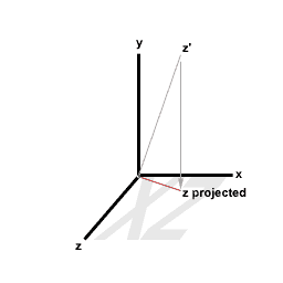
Now I will go on to explain how to get the camera to look at a coordinate in 3D space. We will be given the target as a parameter, and we will rotate the axes accordingly. If the camera is supposed to look at the target then we must orient m_target so that it points at target (note that the parameter target will be an absolute value whereas m_target is relative to the camera's position). Finding m_target is rather simple, just subtract m_position from the target parameter and the result will be a vector pointing from the camera's position to the target! Now on to the more tricky part... We need to determine where our other two axes (X and Y, or right and up) will point. A couple things have to be understood before we can do this. First of all, by taking any two axes we can create a plane. Therefore, since we have three axes we will have three planes, XY, XZ, YZ. Secondly, on each of these planes, the two axes that make up the plane are perpendicular (or, they intersect at 90 degree angles). We must preserve these relationships when we determine our new axes' positions.
We will start off by determining our X axis (right vector). We know that it will be perpendicular to the YZ plane. That's all well and good, but we don't have the Y axis vector needed to form the YZ plane yet, so how can this information help us? The answer is this, we project the Z axis vector (our target vector) onto the XZ plane and use the default Y axis (0, 1, 0) as seen in the picture below. This ensures that the target and up vectors are perpendicular.
Now that we have a plane formed by the default Y axis (0, 1, 0) and our projected Z axis (target vector) we can find our X axis. We can use a cross product to find the vector perpendicular to the plane formed by the default Y axis and the projected Z axis.
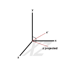
Now that we have our X axis and our Z axis we need to find our Y axis. To do this we must back track a little. We no longer want to use our projected Z axis, but instead we'll use the target vector (relative to the camera's position) and our newly found X axis vector. These two vectors form a plane which the Y axis will be perpendicular to. Simply find the cross product of the new Z axis (target vector) and the new X axis to determine the new Y axis.
Here's the code:
void Camera :: setTarget(Vector target)
{
	Vector projectedTarget;

	target = target - m_position;
	projectedTarget = target;

	if(fabs(target.m_xyzw[0]) < 0.00001f && fabs(target.m_xyzw[2]) < 0.00001f) { // YZ plane

		projectedTarget.m_xyzw[0] = 0.0f;
		projectedTarget.normalize();

		m_right = Vector(1.0f, 0.0f, 0.0f);
		m_up = cross(projectedTarget, m_right);

		m_target = target;
		m_right = -cross(m_target, m_up);
	}

	else { // XZ plane

		projectedTarget.m_xyzw[1] = 0.0f;
		projectedTarget.normalize();

		m_up = Vector(0.0f, 1.0f, 0.0f);
		m_right = -cross(projectedTarget, m_up);

		m_target = target;
		m_up = cross(m_target, m_right);
	}

	m_target.normalize();
	m_right.normalize();
	m_up.normalize();
}
This first block of code makes a vector from the camera's position to the target.
void Camera :: setTarget(Vector target)
{
	Vector projectedTarget;

	target = target - m_position;
The next block of code assigns the value of target to the vector projectedTarget. This vector will be projected onto either the XZ or YZ plane.
projectedTarget = target;
If the X and Z components of the target are 0, a projection onto the XZ plane would create a 0, 0, 0 vector (since in order to project the vector onto the XZ plane the Y component is removed). If we were to then use this 0, 0, 0 vector to determine other vectors everything would get messed up, so we want to avoid this. This if statement catches this condition. If the if statement results in true we will project the vector onto the YZ plane.
if(fabs(target.m_xyzw[0]) < 0.00001f && fabs(target.m_xyzw[2]) < 0.00001f) { // YZ plane
Here we project projectedTarget onto the YZ plane by removing the X component of the vector. Next we normalize it.
		projectedTarget.m_xyzw[0] = 0.0f;
		projectedTarget.normalize();
Now we find the new up vector. We do this by calculating the cross product of the default right vector (1, 0, 0) and the projected vector.
		m_right = Vector(1.0f, 0.0f, 0.0f);
		m_up = cross(projectedTarget, m_right);
Next we calculate the right vector by finding the cross product of the target and the up vector that we just found.
		m_target = target;
		m_right = -cross(m_target, m_up);
	}
If our previous if statement evaluated to false, then we will project our vector onto the XZ plane by removing the Y component and normalizing.
	else { // XZ plane

		projectedTarget.m_xyzw[1] = 0.0f;
		projectedTarget.normalize();
Now we find the new right vector. We do this by calculating the cross product of the up vector (0, 1, 0 which is the default value) and the projectedTarget vector.
	m_up = CEGL_Vector(0.0f, 1.0f, 0.0);
	m_right = -cross(projectedTarget, m_up);
Next we calculate the up vector by finding the cross product of the target and the right vector that we just found.
	m_target = target;
	m_up = cross(m_target, m_right);
Finally we normalize the vectors.
Last updated: August 20/2003
-- Ian Kerr
fredmanjr@hotmail.com
Discuss this article in the forums
Date this article was posted to GameDev.net: 4/20/2003
(Note that this date does not necessarily correspond to the date the article was written)
See Also:
General
© 1999-2011 Gamedev.net. All rights reserved. Terms of Use Privacy Policy
Comments? Questions? Feedback? Click here!