Dynamic 2D Soft Shadows
|
|
ADVERTISEMENT |
The aim of this document is to describe an accurate method of generating soft shadows in a 2D environment. The shadows are created on the fly via geometry as opposed to traditional 2D shadow methods, which typically use shadow sprites or other image based methods. This method takes advantage of several features available in the core OpenGL API, but is by no means restricted to this platform. Direct3D would also be a suitable rendering API, and the concepts and reasoning behind the various rendering stages should hopefully be clear enough that a reader can make the conversion without too much hassle.
Overview
We will start by defining a few terms that we will use frequently, and a brief explanation of the phenomena that we are attempting to reproduce on our digital canvas.
Image 1: Overview of terms
Light source
An obvious place to start – in this implementation we will discuss a point light source, although extending the method to include directional lights as well would be easily done, as is adding ambient lighting into the system. We use a point light source with a user-defined radius to generate the soft shadows accurately.
Shadow caster
A shadow caster is any object that blocks the light emitted from the source. In this article we present implementation details for using convex hulls as shadow casters. Convex hulls have several useful properties, and provide a flexible primitive from which to construct more complex objects. Details of the hulls are discussed in just a bit.
Light range
In reality light intensity over a distance is subject to the inverse square relationship, and so can never really reach zero. In games however linear light fall off often looks as good or better depending on the circumstances. The image above a linear fall off in the intensity is used, dropping to zero at the edge of the light range.
Umbra
The umbra region of a shadow is the area completely hidden from the light source, and as such is a single colour (the image above shows the umbra region in black since there is no other light source to illuminate this region).
Penumbra
The penumbra region of a shadow is what creates the soft edges. This is cast in any area that is partially hidden from the light but neither in full view or totally hidden. The size and shape of the penumbra region is related to the lights position and physical size (not its range).
Core Classes
First we'll have a look at a couple of classes that are at the core of the system – the Light and ConvexHull classes.
Light: The light class is fairly self-explanatory, holding all the information needed to represent a light source in our world.
Contains:
- Position and depth. Fairly obvious, these are the location in the world. Although the system is 2d, we still use a depth for correctly defining which objects to draw in front of which others. Since we'll be using 3D hardware to get nice fast rendering we'll take advantage of the depth buffer for this.
- Physical size and range. Both stored as a simple radial distance, these control how the light influences its surroundings.
- Colour and intensity. Lights have a colour value stored in the standard RGB form, and an intensity value which is the intensity at the centre of the light.
ConvexHull: The convex hull is our primitive shape from which we will construct our world. By using these primitives we are able to construct more complex geometry.
Contains:
- List of points. A simple list is maintained of all the points that make up the edges of the hull. This is calculated from a collection of points and the gift-wrapping algorithm is used to discard unneeded points. The gift-wrapping method is useful since the output geometry typically has a low number of edges. You may want to look into the QuickHull method as an alternative.
- Depth. As for the light, a single depth value is used for proper display of overlapping objects.
- Shadow depth offset. The importance of this is described later.
- Centre position. The centre of the hull is approximated by averaging all the points on the edge of the hull. While not an exact geometric centre it is close enough for our needs.
- Vertex data. Other data associated with the vertex positions. Currently only per-vertex colours but texture cords could be added without requiring any major changes.
Rendering Overview
The basic rendering process for a single frame looks like:
- Clear screen, initialise camera matrix
- Fill z buffer with all visible objects.
- For every light:
- Clear alpha buffer
- Load alpha buffer with light intensity
- Mask away shadow regions with shadow geometry
- Render geometry with full detail (colours, textures etc.) modulated by the light intensity.
The essential point from the above is that a rendering pass is performed for every visible light, during which the alpha buffer is used to accumulate the lights intensity. Once the final intensity values for the light have been created in the alpha buffer, we render all the geometry modulated by the values in the alpha buffer.
Simple Light Attenuation
First we'll set up the foundation for the lighting – converting the above pseudo code into actual code but without the shadow generation for now.
public void render(Scene scene, GLDrawable canvas)
{
  GL gl = canvas.getGL();

  gl.glDepthMask(true);
  gl.glClearDepth(1f);
  gl.glClearColor(0.0f, 0.0f, 0.0f, 0.0f);
  gl.glClear(GL.GL_COLOR_BUFFER_BIT |
             GL.GL_DEPTH_BUFFER_BIT |
             GL.GL_STENCIL_BUFFER_BIT);

  gl.glMatrixMode(GL.GL_PROJECTION);
  gl.glLoadIdentity();
  gl.glMatrixMode(GL.GL_MODELVIEW);
  gl.glLoadIdentity();
  gl.glMatrixMode(GL.GL_TEXTURE);
  gl.glLoadIdentity();

  gl.glDisable(GL.GL_CULL_FACE);


  findVisibleLights(scene);

  Camera activeCamera = scene.getActiveCamera();
  activeCamera.preRender(canvas);
  {
    // First we need to fill the z-buffer
    findVisibleObjects(scene, null);

    fillZBuffer(canvas);


    // For every light
    for (int lightIndex=0; lightIndex<visibleLights.size(); lightIndex++)
    {
      Light currentLight = (Light)visibleLights.get(lightIndex);

      // Clear current alpha
      clearFramebufferAlpha(scene, currentLight, canvas);

      // Load new alpha
      writeFramebufferAlpha(currentLight, canvas);

      // Mask off shadow regions
      mergeShadowHulls(scene, currentLight, canvas);

      // Draw geometry pass
      drawGeometryPass(currentLight, canvas);
    }

    // Emmissive / self illumination pass
    // ..

    // Wireframe editor handles
    drawEditControls(canvas);

  }
  activeCamera.postRender(canvas);
}
Note that code here is written in Java, using the Jogl set of bindings to OpenGL. For C++ programmers you simply have to remember that primitives such as int, float, boolean etc. are always passed by value, and objects are always passed by reference. OpenGL commands and enumerations are scoped to a GL object, which leads to the slightly extended notation from the straight C style.
First we reset the GL state ready for the next frame, collect all the lights that we will need to render this frame and retrieve the currently active camera from the scene. Camera.preRender() and .postRender() are used to set the modelview and projection matrices to that needed for the view position.
Once this initialisation is complete we need to fill the z-buffer for the whole scene. Although not discussed here, this would be the perfect place to take advantage of your favourite type of spatial tree. A quad-tree or AABB-tree would make a good choice for inclusion within the scene, and would be used for all testing of objects against the view frustum. To fill the depth buffer we simply enable z-buffer reading and writing, but with colour writing disabled to leave the colour buffer untouched. This creates a perfect depth buffer for us to use and stops later stages blending pixels hidden from view. It is worth noting that by enabling colour writing an ambient lighting pass can be added here to do both jobs at the same time. From this point onwards we can disable depth writing as it no longer needs to be updated.
Now we perform a rendering pass for every light.
First the alpha buffer is cleared in preparation for its use. This is simply a full screen quad drawn without blending, depth testing or colour writing to reset the alpha channel in the framebuffer to 0f. Since we don't want to disturb the current camera matrices that have been set up, we create this quad by using the current camera position to determine the quads coordinates.
Next we need to load the lights intensity into the alpha buffer. This does not need any blending, but depth testing is enabled this time to allow lights to be restricted to illuminating only the objects beneath them. Again colour writing is left disabled since we are not ready to render any visible geometry yet. The following function is used to create the geometry for a single light:
public void renderLightAlpha(float intensity, GLDrawable canvas)
{
  assert (intensity > 0f && intensity <= 1f);

  GL gl = canvas.getGL();
  int numSubdivisions = 32;

  gl.glBegin(GL.GL_TRIANGLE_FAN);
  {
    gl.glColor4f(0f, 0f, 0f,  intensity);
    gl.glVertex3f(center.x, center.y, depth);

    // Set edge colour for rest of shape
    gl.glColor4f(0f, 0f, 0f, 0f);

    for (float angle=0; angle<=Math.PI*2; angle+=((Math.PI*2)/numSubdivisions) )
    {
      gl.glVertex3f( radius*(float)Math.cos(angle) + center.x,
                     radius*(float)Math.sin(angle) + center.y, depth);
    }

    gl.glVertex3f(center.x+radius, center.y, depth);
  }
    gl.glEnd();
}
What happens is we create a triangle fan rooted at the centre position of the light, then loop around in a circle creating additional vertices as we go. The alpha value of the centre point is our light intensity, fading linearly to zero on the edges of the circle. This creates the smooth light fall off seen in the first image. If other methods of light attenuation are needed, they can be generated here. An interesting alternative would be to use an alpha texture instead of vertex colours; a 1D texture could happily represent a non-linear set of light intensities. Other unusual effects could be achieved by animating the texture coordinates over a 2D texture, such as flickering candlelight or a pulsing light source.
So now we have our light intensity values in the alpha buffer, we will skip the generation of shadow hulls for the moment and move on to getting our level geometry up on the screen.
The geometry pass is where we really start to see things coming together, using the results we have carefully composed in the alpha of the framebuffer. First we need to make sure we have depth testing enabled (using less-than-or-equals as before), and then enable and set up our blending equation correctly.
  gl.glEnable(GL.GL_BLEND);
  gl.glBlendFunc(GL.GL_DST_ALPHA, GL.GL_ONE);
Simple, yes? What we're doing here is multiplying our incoming fragments (from the geometry we're about to draw) by the alpha values already sitting in the framebuffer. This means any alpha values of 1 will now be drawn at full intensity, and values of 0 being unchanged. This is then added to the current framebuffer colour multiplied by one. This addition to the existing colour means we slowly accumulate our results from previous passes. With our blend equation set up, we simply render our geometry as normal, using whatever vertex colours and textures that takes our fancy.
If you take another look at our render() function near the top, you'll see we've almost finished composing our frame. Once we've looped over all the lights we've practically finished, but we'll insert a couple of extra stages. First an emissive or self illumination pass – this is discussed near the end of the article. After this is a simple wireframe rendering with draws object outlines such as seen in the first image.
Image 2: Per pixel lighting with intensities accumulated in the alpha buffer.
Coloured Lighting
What was once seen as 'the next big thing' in the Quake 2 and Unreal era, coloured lighting is pretty much standard by now, and a powerful tool for level designers to add atmosphere to a scene. Now since we've already got our light intensity ready and waiting for our geometry in the alpha buffer, all we need to do is modulate the geometry colour by the current light colour while drawing. That's a whole lot of multiplication if we want to do it ourselves, but on TnL hardware we can get it practically for free with a simple trick. We enable lighting while drawing our geometry; yet define no normals for we have no need of them. Instead we just enable a single light and set its ambient colour to the colour of our current light. The graphics card will calculate the effect of the light colour on our geometry for us and we need barely lift a finger. Note that because we're accumulating light intensities over multiple lights in the framebuffer we get accurate over brightening effects when lights overlap, and multiple coloured lights will merge and produce white illumination of our objects.
Hard-edged Shadow Casting
Now we have our lights correctly illuminating their surroundings we can start thinking about correctly limiting their light to add shadows into the scene. First we will cast hard edged shadows from shadow casters and then extend this to cover soft edged shadows with correct umbra and penumbra. This is done in the function we previously skipped, mergeShadowHulls().
You will remember that at this point in the rendering we have the light intensity stored in the alpha buffer. Now what we will do is create geometry to represent the shadow from each shadow caster, then merge this into the alpha buffer. This is done inside the ConvexHull class.
Finding the boundary points
Our first step is to determine which points our shadow should be cast from. The list of points that make up the ConvexHull is looped though, and each edge is classified in regard to the light position. In pseudo code:
- For every edge:
- Find normal for edge<
- Classify edge as front facing or back facing
- Determine if either edge points are boundary points or not.
The normal for the edge is found as:
float nx = currentPoint.y - prevPoint.y;
float ny = currentPoint.x - prevPoint.x;
Then a dot product is performed with this vector and the vector to the light. If this is greater than zero, the edge is front facing. Once and edge has been classified, it is compared against the previous edge. If one is front facing and the other back facing, then the shared vertex is a boundary point. As we walk around the edge of the hull (in an anti-clockwise direction) the boundary point from light to shadow is the start shadow point. The boundary from shadow to light is the end shadow point.
Creating the Shadow Geometry
Once we have these positions, we can generate our shadow geometry. Since we are only generating hard edged shadows at the moment, we will be ignoring the physical size of our light source. Image 3 shows a how the shadow geometry is built.
Image 3: Hard-edged shadow generation
As shown in the image, the shadow geometry is a single triangle strip projected outwards from the back facing edges of the shadow caster. We start at the first boundary point (marked with a red cross) and work our way anti-clockwise. The second point is found by finding the vector from the light to the point, and using this to project the point away from the light. A projection scale amount is used to ensure that the edges of the shadow geometry are always off screen. For now we can simply set this to a sufficiently large number, but later it will be advantageous to calculate this every frame depending on how far zoomed in or out the camera is.
We render the shadow geometry with depth testing enabled to properly layer the shadow between various other objects in the world, but with colour writing disabled, only the alpha in the framebuffer is changed. You may remember that the final geometry pass is modulated (multiplied) by the existing alpha values, which means we need to set the shadow to have an alpha value of zero. Because the framebuffer will clamp the values to between one and zero, overlapping shadows will not make an affected area too dark but instead merge correctly.
Image 4 : Hard-edged shadows
Notice in image 4 how the shadow from the red diamond correctly obscures the green object, and that their shadows are correctly merged where they overlap.
Soft-Edged Shadow Casting
Now we can properly construct hard edged shadows it is time to extend this to cover soft shadows – note that we cannot simply add faded edges to the existing shadow geometry, since this would result in inaccurate penumbra and umbra regions. First we start by defining a physical radius for the light source to generate the correct penumbra regions, then we need to create the penumbra geometry and modify the creation of the umbra region that we used for the hard edged shadows.
Shadow Fins
Each penumbra region will be created by one or more shadow fins via that ConvexHull and ShadowFin classes.
ShadowFin: An object to encompass all or part of a penumbra region.
Contains:
- Root position. This is the position from which the fin protrudes from.
- Penumbra vector. This is a vector from the root position which lies on the outer edge of the fin (the highest light intensity).
- Umbra vector. This vector from the root position lies on the inner edge of the fin (lowest light intensity).
- Penumbra and umbra intensities. These are the light intensities of their relative edges for the fin. If the fin makes up an entire penumbra region these are one and zero respectively.
We start at the first boundary point, and create a ShadowFin from this point. The root position becomes the boundary point, and the penumbra and umbra intensities are initially one and zero. The difficult part of the fin – the penumbra and umbra vectors – is done by the getUmbraVector and getPenumbraVector methods within our Light object.
Image 5 : Shadow fin generation
If we look at the vector that lies along the outer penumbra edge we can imagine it as the vector from the light though the boundary point (C, the centre vector) displaced by the light radius. So we must find this displacement.
First we note that the displacement is as right angles to the centre vector. So we take C and find this perpendicular vector in the same way we did to find the normals for the hull edges. Now although looking at the diagram we know which way we want this to point, when we're dealing with boundary points and light positions at all sorts of funny angles to each other we may end up with it pointing in the opposite direction to that which we expect. To solve this we find the vector from the centre of the hull to the boundary point (between the two Xs in the image), and take the dot product of this and the perpendicular vector. If this is less than zero, our vector is pointing in the wrong direction and we invert it.
Armed with this new vector we normalise it and the centre vector, then add them together and we've found our crucial outer penumbra vector. Finding the inner vector requires we repeat the process but this time we invert the logic for the dot product test to displace the centre vector in the opposite direction. We now have a fully calculated shadow fin to send to our renderer!
Non-Linear Shading
Although we have all the numbers we need to render our shadow fin, we'll soon hit a major snag – we can't use regular old vertex colours this time to write to the alpha buffer. We need the inner edge of the penumbra to be zero intensity (zero alpha) and our outer edge to be fully bright (alpha of one). While you can probably visualise that easily, getting our graphics card to actually render a triangle with the colours like this just isn't possible. Try it yourself if you're not sure, you'll soon see how it's the root point that causes the problems – it lies on both edges, so needs to be 'both' zero and one at the same time.
The solution to this (and indeed most cases when you need non linear shading) is to abandon vertex colours for the fins and instead use a texture to hold the information. Below is a copy of the texture I used.
Image 6 : Penumbra texture
You can clearly see how the shadow fin will be rooted at the bottom left, and the two edges running vertical and diagonally to the top edge. Also note the line of white pixels along the right side, this prevents blending artefacts along the vertical edge. The bottom right half of the texture is unused, although if you really wanted to you could pack something else in here just as long as you're careful not to bleed over the edge.
So we load this texture and bind it for use before drawing our shadow fins, and set the vertex colour to white to leave the texture unchanged by it. Other than that rendering the fins is no different from the shadow hull. The only other thing we need to watch out for is how far back we project our points by the umbra/penumbra vectors, as the limited resolution of our penumbra texture will show if these are moved too far away. Ideally they will be projected to just off screen.
Modifying the umbra generation
Now we've got the fins drawn, we can fill in the umbra between them. This is done in almost exactly the same way as with hard shadows, except we must use the fins inner edges to start and finish from instead of directly projecting away from the centre of the light source. As we move across the back of the shadow caster, we perform a weighted average between these two edge vectors to properly fill in the umbra region. When done correctly we see no gaps between the fins and the umbra geometry, giving us one consistent, accurate shadow cast into the alpha buffer.
Making it robust
Self-Intersection
Now we have this far implemented, the shadows will be looking quite nice – when static – however problems will become apparent when moving the light sources around. The most glaring is that of self-intersection.
Image 7 : Self intersection of shadow fin
If the light source is too large in relation to the object, or too near, the inner penumbra edge will intersect the hull. First we need to detect this case. We find the vector from the boundary point to the next edge point in the shadow (moving anti clockwise here since we're on the shadow start boundary point). Then we compare the angle between the outer penumbra edge and our newly found hull edge, and the angle between the outer and inner penumbra edges. If the angle to the boundary edge is smaller, the we've got an intersection case we need to fix.
First we snap the current fin to the boundary edge, and calculate the new intensity for the inner edge via the ratio of the angles. Then we create a new shadow fin at the next point on the hull. This has an outer edge set to the same vector and intensity as the existing fins inner edge, while the new fins inner edge is calculated as before. By gluing these two fins together we create a single smooth shadow edge. Technically we should repeat the self-intersection test and keep adding more fins as needed, however I've not found that this is needed in practice.
Eliminating 'Popping'
You will also notice one other problem with this as it stands, the shadow fins will 'pop' along the edges of the hull as a light rotates. This is because we're still using an infinitely small point light to find the boundary points. To solve this we should take the physical radius into account when finding them. A robust way of doing this is to shift the light source position towards the hull by the radius distance before we find our boundary points. With these two fixes in place the fins will be visually stable as either the light or the hull moves (or both!).
Depth Offset
Depending on the style of game and the view used (such as a side scrolling platformer as opposed to a top down shooter) the way light and shadow interacts with the various level objects will be different. What seems sensible for one may appear wrong in another. Most obviously is with objects casting shadows onto objects at the same depth.
Image 8 : The effect of shadow offset
The image above shows the same scene with different shadow offsets. Imagine that the scene is a top down viewpoint – the grey areas are impassable walls while the green-grey is the floor showing a T junction (imagine hard!). Now the image on the right seems slightly out of place – the shadows are being projected on top of the walls, yet these are much higher than the light source – realistically they shouldn't be lit at all but solid black walls aren't very visually appealing. The second shows the shadows being offset and only obscuring the floor and any objects on it.
Now if you were to imagine the same scene as a 2D platformer, you might prefer the left image. Here it seems to make more sense that the objects should shadow those on the same level. This decision is usually very dependant on the geometry and art direction of the level itself, so no hard and fast rules seem to apply. The best option seems to be to experiment and see which looks best.
Adding control over this is a small modification. At the moment the scene on the left is the common case, and by generating shadow volumes that are a close fit to the edge of the shadow caster we've already done all the hard work, all we need to do is store a shadow depth offset in our ConvexHull and apply it to the depth of the shadow geometry. The existing depth testing will reject fragments drawn behind other objects and leave them at the original intensity.
Emmissive / Self Illumination pass
This is a simple addition that can produce some neat effects – and can be seen as a generalisation of the wireframe 'full-bright' pass. After the lights have been drawn, we clear the alpha buffer again as before, but instead of writing light intensities into it we render our scene geometry with their associated emissive surface. This is an alpha texture used to control light intensities as before, and can be used for glowing objects, such as a computer display or a piece of hardware with a bank of LEDs - everything that has its own light source but is too small to require an individual light of its own. Because these are so small, we skip the shadow generation and can do them all in one go. Then we modulate the scene geometry by this alpha intensity as before. Unusual effects are possible with this, such as particles which light up their immediate surroundings, or the bright local illumination provided by a neon sign (with one or two associated lights to provide the lighting at medium and long range).
Conclusion
After a lot of work, much maths and a few sneaky tricks and we've finally got a shadow system that's both physically accurate and robust. The hardware requirements are modest indeed – a framebuffer with an alpha component is about all that's required, we don't even need to stray into extensions to get the correct effect. There is a whole heap of possible optimisations and areas for improvement, notably caching the calculated shadow geometry when neither the light nor the caster has changed, and including some sort of spatial tree so that only the shadow casters that are actually needed are used for each light.
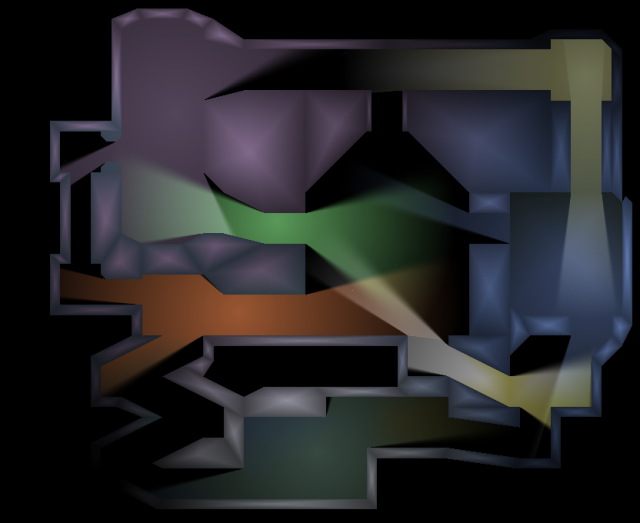
Image 9 : The final system in action! A total of 7 lights used here.
Discuss this article in the forums
Date this article was posted to GameDev.net: 1/4/2004
(Note that this date does not necessarily correspond to the date the article was written)
See Also:
Featured Articles
Shadows
© 1999-2011 Gamedev.net. All rights reserved. Terms of Use Privacy Policy
Comments? Questions? Feedback? Click here!