Soft-Edged Shadow Casting
Now we can properly construct hard edged shadows it is time to extend this to cover soft shadows – note that we cannot simply add faded edges to the existing shadow geometry, since this would result in inaccurate penumbra and umbra regions. First we start by defining a physical radius for the light source to generate the correct penumbra regions, then we need to create the penumbra geometry and modify the creation of the umbra region that we used for the hard edged shadows.
Shadow Fins
Each penumbra region will be created by one or more shadow fins via that ConvexHull and ShadowFin classes.
ShadowFin: An object to encompass all or part of a penumbra region.
Contains:
- Root position. This is the position from which the fin protrudes from.
- Penumbra vector. This is a vector from the root position which lies on the outer edge of the fin (the highest light intensity).
- Umbra vector. This vector from the root position lies on the inner edge of the fin (lowest light intensity).
- Penumbra and umbra intensities. These are the light intensities of their relative edges for the fin. If the fin makes up an entire penumbra region these are one and zero respectively.
We start at the first boundary point, and create a ShadowFin from this point. The root position becomes the boundary point, and the penumbra and umbra intensities are initially one and zero. The difficult part of the fin – the penumbra and umbra vectors – is done by the getUmbraVector and getPenumbraVector methods within our Light object.
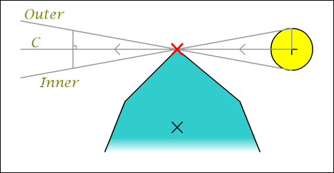
Image 5 : Shadow fin generation
If we look at the vector that lies along the outer penumbra edge we can imagine it as the vector from the light though the boundary point (C, the centre vector) displaced by the light radius. So we must find this displacement.
First we note that the displacement is as right angles to the centre vector. So we take C and find this perpendicular vector in the same way we did to find the normals for the hull edges. Now although looking at the diagram we know which way we want this to point, when we're dealing with boundary points and light positions at all sorts of funny angles to each other we may end up with it pointing in the opposite direction to that which we expect. To solve this we find the vector from the centre of the hull to the boundary point (between the two Xs in the image), and take the dot product of this and the perpendicular vector. If this is less than zero, our vector is pointing in the wrong direction and we invert it.
Armed with this new vector we normalise it and the centre vector, then add them together and we've found our crucial outer penumbra vector. Finding the inner vector requires we repeat the process but this time we invert the logic for the dot product test to displace the centre vector in the opposite direction. We now have a fully calculated shadow fin to send to our renderer!
Non-Linear Shading
Although we have all the numbers we need to render our shadow fin, we'll soon hit a major snag – we can't use regular old vertex colours this time to write to the alpha buffer. We need the inner edge of the penumbra to be zero intensity (zero alpha) and our outer edge to be fully bright (alpha of one). While you can probably visualise that easily, getting our graphics card to actually render a triangle with the colours like this just isn't possible. Try it yourself if you're not sure, you'll soon see how it's the root point that causes the problems – it lies on both edges, so needs to be 'both' zero and one at the same time.
The solution to this (and indeed most cases when you need non linear shading) is to abandon vertex colours for the fins and instead use a texture to hold the information. Below is a copy of the texture I used.
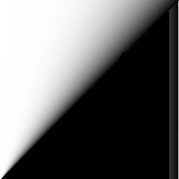
Image 6 : Penumbra texture
You can clearly see how the shadow fin will be rooted at the bottom left, and the two edges running vertical and diagonally to the top edge. Also note the line of white pixels along the right side, this prevents blending artefacts along the vertical edge. The bottom right half of the texture is unused, although if you really wanted to you could pack something else in here just as long as you're careful not to bleed over the edge.
So we load this texture and bind it for use before drawing our shadow fins, and set the vertex colour to white to leave the texture unchanged by it. Other than that rendering the fins is no different from the shadow hull. The only other thing we need to watch out for is how far back we project our points by the umbra/penumbra vectors, as the limited resolution of our penumbra texture will show if these are moved too far away. Ideally they will be projected to just off screen.
Modifying the umbra generation
Now we've got the fins drawn, we can fill in the umbra between them. This is done in almost exactly the same way as with hard shadows, except we must use the fins inner edges to start and finish from instead of directly projecting away from the centre of the light source. As we move across the back of the shadow caster, we perform a weighted average between these two edge vectors to properly fill in the umbra region. When done correctly we see no gaps between the fins and the umbra geometry, giving us one consistent, accurate shadow cast into the alpha buffer.

Making it robust
|