Pixel Shader Tools
I already introduced Shader Studio, Shader City, DLL Detective, 3D Studio Max 4.x/gmax, NVASM, the Effectsbrowser, the Shader Debugger and the Photoshop plug-ins from NVIDIA in the first part. There is one thing to remember specific for pixel shaders: because the GeForce 4TI supports ps.1.1 - ps.1.3, it is possible, that a few of the NVIDIA tools won't support ps.1.4. Additonally there are the following pixel shader-only tools:
Microsoft Pixel Shader Assembler
The pixel shader assembler is provided with the DirectX 8.1 SDK. Like with it's pendant the vertex shader assembler it does not come with any documentation. Its output look like this:

Figure 4 - Pixel Shader Assembler Output
The pixel shader assembler is used by the Direct3DX functions that compile pixel shaders and can also be used to pre-compile pixel shaders.
MFC Pixel Shader
The MFC Pixel Shader example provided with the DirectX 8.1 SDK comes with source. It is very useful for trying out pixel shader effects in a minute and debugging them. Just type in the pixel shader syntax you want to test and it will compile it at once. Debugging information is provided in the window at the bottom. If your graphics card doesn't support a particular pixel shader version, you can always choose the reference rasterizer and test all desired pixel shader versions. In the following picture the reference rasterizer was chosen on a GeForce 3 to simulate ps.1.3:
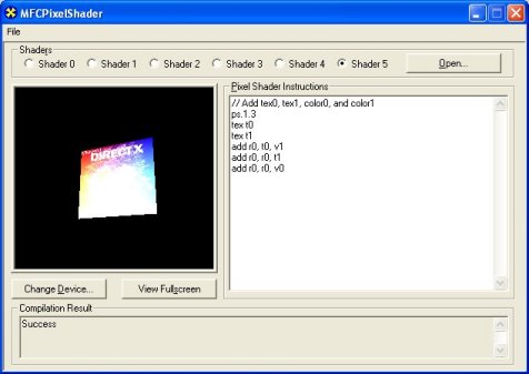
Figure 5 - MFCPixelShader
ATI ShadeLab
The ATI Shadelab helps designing pixel shaders. After writing the pixel shader source into the big entry field in the middle, the compilation process starts immediately. To be able to load the pixel shader later, it has to be saved with the <Save> button and loaded with the <Load> button.

Figure 6 - ATI ShadeLab
You may set up to six textures with specific texture coordinates and the eight constant registers. The main advantage over the MFC Pixel Shader tool is the possibility to load constant registers and the textures on your own. This tool is provided on the Book DVD in the directory <Tools>.
With that overview on the available tools in mind, we can go one step further by examining a diagram with the pixel shader workflow.
Pixel Shader Architecture
The following diagram shows the logical pixel shader data workflow. All the grey fields mark functionality specific for ps.1.1 - ps.1.3. The blue field marks functionality that is specific to ps.1.4.
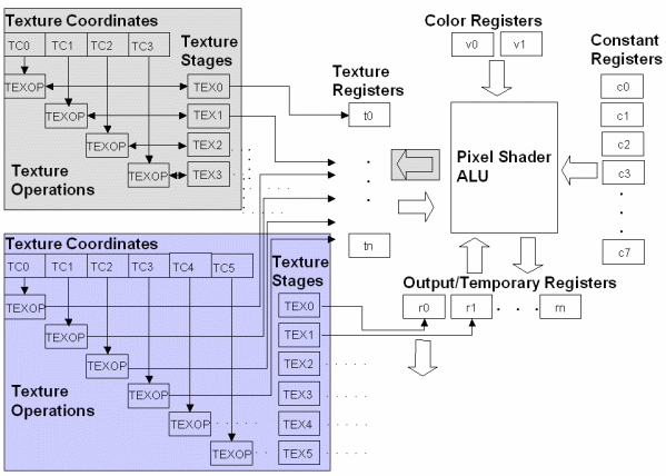
Figure 7 - Pixel Shader logical Data Flow
On the right half of the diagram the pixel shader arithmetic logic unit (ALU) is surrounded by four kinds of registers. The Color Registers stream iterated vertex color data from a vertex shader or a fixed-function vertex pipeline to a pixel shader. The Constant Registers provide constants to the shader, that are loaded by using the SetPixelShaderConstant() function or in the pixel shader with the def instruction. The Temporary Registers rn are able to store temporay data. The r0 register also serves as the Output register of the pixel shader.
The Texture Coordinates can be supplied as part of the vertex format or can be read from certain kind of texture maps. Texture coordinates are full precision and range as well as perspective correct, when used in a pixel shader. There are D3DTSS_* Texture Operations that are not replaced by the pixel shader functionality, they can be used on the up to four (ps.1.1 - ps.1.3) or six textures (ps.1.4). The Texture Stages are holding a reference to the texture data that might be a one-dimensional (for example in a cartoon shader), two-dimensional or three-dimensional texture (volume textures or cube map). Each value in a texture is called a texel. These texels are most commonly used to store color values, but they can contain any kind of data desired including normal vectors for bump maps, shadow values, or general look-up tables.
Sampling occurs, when a texture coordinate is used to address the texel data at a particular location with the help of the Texture Registers. The usage of the texture registers tn differ between the ps.1.1 - ps.1.3 (t0 - t3) and the ps.1.4 (t0 - t5) implementations.
In case of ps.1.1 - ps.1.3 the association between the texture coordinate set and the texture data is a one-to-one mapping, which is not changeable in the pixel shader. Instead this association can be changed by using the oTn registers in a vertex shader or by using the texture stage state flag TSS_TEXCOORDINDEX together with SetTextureStageState(), in case the fixed function pipeline is used.
In ps.1.4, the texture data and the texture coordinate set can be used independent of each other in a pixel shader. The texture stage from which to sample the texture data is determined by the register number rn and the texture coordinate set, that should be used for the texture data is determined by the number of the tn register specified.
Let's take a closer look at the different registers shown in the upper diagram:
| Type |
Name |
ps.1.1 |
ps.1.2 |
ps.1.3 |
ps.1.4 |
Read/Write Caps |
| Constant Registers |
cn |
8 |
8 |
8 |
8 |
RO |
| Texture Registers |
tn |
4 |
4 |
4 |
6 |
RW / ps.1.4: RO |
| Temporary Registers |
rn |
2 |
2 |
2 |
6 |
RW |
| Color Registers |
vn |
2 |
2 |
2 |
2 in Phase 2 |
RO |
Constant Registers (c0 - c7)
There are eight constant registers in every pixel shader specification. Every constant register contains four floating point values or channels. They are read-only from the perspective of the pixel shader, so they could be used as a source register, but never as destination registers in the pixel shader. The application can write and read constant registers with calls to SetPixelShaderContant() and GetPixelShaderConstant(). A def instruction used in the pixel shader to load a constant register, is effectively translated into a SetPixelShaderConstant() call by executing SetPixelShader().
The range of the constant registers goes from -1 to +1. If you pass anything outside of this range, it just gets clamped. Constant registers are not usable by ps.1.1 - ps.1.3 texture address instructions except for the texm3x3spec, which uses a constant register to get an eye-ray vector.
Output and Temporary Registers (ps.1.1 - ps.1.3: r0 + r1; ps.1.4: r0 - r5)
The temporary registers r0 - rn are used to store intermediate results. The output register r0 is the destination argument for the pixel shader instruction. So r0 is able to serve as a temporary and output register. In ps.1.4 r0 - r5 are also used to sample texture data from the texture stages 0 - 5 in conjunction with the texture registers. In ps.1.1 - ps.1.3, the temporary registers are not usable by texture address instructions.
CreatePixelShader() will fail in shader pre-processing if a shader attempts to read from a temporary register that has not been written to by a previous instruction. All shaders have to write to r0.rgba the final result or the shader will not assemble or validate.
Texture Registers (ps.1.1 - ps.1.3: t0 - t3; ps.1.4: t0 - t5)
The texture registers are used in different ways in ps.1.1 - ps.1.3 and in ps.1.4. In ps.1.1 - ps.1.3 the usage of one of the t0 - t3 texture registers determine the usage of a specific pair of texture data and texture coordinates. You can't change this one-to-one mapping in the pixel shader:
ps.1.1     // version instruction
tex t0     // samples the texture at stage 0
           // using texture coordinates from stage 0
mov r0, t0 // copies the color in t0 to output register r0
tex samples the texture data from the texture stage 0 and uses the texture coordinates set, that is set in the vertex shader with the oTn registers. In ps.1.4, having texture coordinates in their own registers means that the texture coordinate set and the texture data are independant from each other. The texture stage number with the texture data from which to sample is determined by the destination register number (r0 - r5) and the texture coordinate set is determined by the source register (t0 - t5) specified in phase 1.
ps.1.4          // version instruction
texld r4, t5
mov r0, r4
The texld instruction samples the map set via SetTexture (4, lpTexture) using the sixth set of texture coordinates (set in the vertex shader with oT5) and puts the result into the fifth temporary register r4.
Texture registers that doesn't hold any values will be sampled to opaque black (0.0, 0.0, 0.0, 1.0). They can be used as temporary registers in ps.1.1 - ps.1.3. The texture coordinate registers in ps.1.4 are read-only and therefore not usable as temporary registers.
The maximum number of textures is the same as the maximum number of simultaneous textures supported (MaxSimultaneousTextures flag in D3D8CAPS).
Color Registers (ps.1.1 - ps.1.4: v0 + v1)
The color registers can contain per-vertex color values in the range 0 through 1 (saturated). It is common to load v0 with the vertex diffuse color and v1 with the specular color.
Using a constant color (flat shading) is more efficient than using an per-pixel Gouraud shaded vertex color. If the shade mode is set to D3DSHADE_FLAT, the application iteration of both vertex colors (diffuse and specular) is disabled. But regardless of the shade mode, fog will still be iterated later in the pipeline.
Pixel shaders have read-only access to color registers. In ps.1.4 color registers are only available during the second phase, which is the default phase. All of the other registers are available in every of the two phases of ps.1.4.
Range
One reason for using pixel shaders is compared to the multitexturing unit, its higher precision that is used by the pixel shader arithmetic logic unit.
| Register Name |
Range |
Versions |
| cn |
-1 to +1 |
all versions |
| rn |
-D3DCAPS8.MaxPixelShaderValue to D3DCAPS8.MaxPixelShaderValue |
all versions |
| tn |
-D3DCAPS8.MaxPixelShaderValue to D3DCAPS8.MaxPixelShaderValue |
ps.1.1 - ps.1.3 |
| -D3DCAPS8.MaxTextureRepeat to D3DCAPS8.MaxTextureRepeat |
ps.1.4 |
| vn |
0 to +1 |
all versions |
The color register vn are 8bit precision per channel, ie 8bit red, 8bit green etc.. For ps.1.1 to ps.1.3, D3DCAPS8.MaxPixelShaderValue is a minimum of one, whereas in ps.1.4 D3DCAPS8.MaxPixelShaderValue is a minimum of eight. The texture coordinate registers provided by ps.1.4 use high precision signed interpolators. The DirectX caps viewer reports a MaxTextureRepeat value of 2048 for the RADEON 8500. This value will be clamped to MaxPixelShaderValue, when used with texcrd, because of the usage of a rn register as the destination register. In this case it is safest to stick with source coordinates within the MaxPixelShaderValue range. However, if tn registers are used for straight texture lookups (i.e. texld r0, t3), then the MaxTextureRepeat range should be expected to be honored by hardware.
Using textures to store color values leads to a much higher color precision with ps.1.4.

High Level View
|