The Evolution of a Cartoon Renderer
The cartoon renderer discussed in this article has been through many incarnations. A great deal of research and experimentation went into developing the current implementation of both the painting and inking components of the renderer. While the details of the different methods I have tested are beyond the scope of this article, more information about these methods accompanies the sample program and source code available from here. With that brief caveat, let's get our hands dirty with the renderer itself.
Painting
The first part of our cartoon renderer is the painter. As a minimum, a painter needs to support rendering an object with solid colors. A more advanced painter will generate stepped shadows and highlights using light direction, vary this shading with brightness, and even support multiple light sources.
Displaying objects with solid colors is rather trivial, but some research has been done into different stepped shading techniques. According to Claes [1], it is possible to choose a constant color (either highlight or shadow) for each polygon, but better results occur if some polygons are subdivided into two shades using linear interpolation. In order to use programmable hardware to achieve a similar effect, it is necessary to use the light direction vector and vertex normal to to sample a specialized shading texture. This is similar to the algorithm used by Lake [2].
The simplest hardware implementation of a painting algorithm that supports stepped shading uses a one-dimensional texture. A vertex program takes the direction of a single light and calculates the dot-product between the light and the vertex normal. A value of one means that the two vectors point in exactly the same direction, but as the angle between the two vectors increases, the value decreases. We can clamp the negative values to zero and use this result as a texture coordinate. A coordinate of 1.0 represents normals that are facing the light and should be bright, and a coordinate of 0.0 will represent normals that are facing away from the light and should be dark.
Our painter improves on this basic algorithm in three ways. Firstly, we calculate the dot-product per-pixel instead of per-vertex. This smoothes jagged shadow lines that can appear on low-poly models. Secondly, we support two directional lights for each mesh. Thirdly, we scale the texture coordinates with the brightness of the light, allowing brighter lights to expand the highlighted areas or even use an extra highlight shade.
The relevant part of the vertex program for our painter is shown in listing 1. It puts the transformed vertex normal into the first set of texture coordinates and the angle of the two lights in the second and third sets of texture coordinates. The light vectors are scaled by the brightness of the light before they are passed to the vertex program. This has the effect of scaling the eventual dot-product between the light and normal vectors.
Listing 1
vs.1.1  ; painter vertex shader
dcl_normal v3

; transform normal
dp3 r1.x, v3, c[INVERSE_WORLD_MATRIX]
dp3 r1.y, v3, c[INVERSE_WORLD_MATRIX_1]
dp3 r1.z, v3, c[INVERSE_WORLD_MATRIX_2]

; renormalize it
dp3 r1.w, r1, r1
rsq r1.w, r1.w
mul r1, r1, r1.w

; stick normal vector in first stage
mov oT0, r1

; stick first light position in second stage
mov oT1, c[LIGHT_POSITION_A]

; stick second light position in third stage
mov oT2, c[LIGHT_POSITION_B]
Most of the work is done in the pixel program that is shown in listing 2. The first stage contains a normalizing cube-map. This is a specialized cube-map that converts interpolated normal values into renormalized values biased into the 0.0 to 1.0 range. This is more accurate than using the texcoord instruction to grab the coordinates directly, as linearly interpolated values can result in vectors with lengths less than one. Figure 1 shows how this occurs. The _bx2 instruction modifier is used to return the vectors into the proper range when they are needed for calculations.
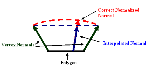
Figure 1: Because the vertex normal is passed to the pixel shader in texture coordinates, it is linearly interpolated per pixel. This interpolated value follows the blue line, leading to non-normalized values on smoothed polygons. The proper normal should follow the red line.
Listing 2
ps.1.1 ; painter pixel shader

def c0, 0.0f, 0.0f, 0.0f, 0.75f   ; light scale
def c1, 0.0f, 0.0f, 0.0f, 1.0f    ; black

tex t0                 ; grab the normalized normal
                       ; normalizing cube map is in t0
texm3x2pad t1, t0_bx2  ; dot with light a for u value
texm3x2tex t2, t0_bx2  ; dot with light b for v value
                       ; 2d shade texture is in stage t2
tex t3                 ; regular texture data

mov r0, C_MATERIAL_DIFFUSE  ; load constant color in
cnd r0, r0.a, r0, t3        ; if alpha, use color
                            ; else, use texture
mul r1.rgb, r0, t2          ; modulate with shading

mul r0.rgb, C_LIGHT_COLOR, c0.a ; scale down light value
mul_x2 r0.rgb, r0, r1           ; modulate x2 with light color
The texm3x2pad and texm3x2tex instructions are used to perform the dot-products between the light angles and the normal. The resulting two scalars are used as u and v coordinates to sample the shading texture which is placed in the third stage. As seen in figure 2, the shading texture has dark pixels at (u=0, v=0) and lightens in steps as the values increase to (u=1, v=1). The number of steps and their relative size is determined by the texture, so it is easy to create a completely different shading style by swapping in a new one.

Figure 2: The shading texture used by our painter. Shadow shades appear in the upper left corner and lighten toward the right and bottom of the texture.
Remember that the light angle is scaled by the brightness of the light, so a half-bright light will generate texture coordinates lower than 0.5. It is therefore possible to create a highlight shade that only shows up around bright lights. This scaling also makes it possible for one of the two lights that are illuminating the model to appear brighter than the other.
Our shading is modulated with either a constant color from the material or the sample from the fourth texture stage, which can contain a standard texture. We then modulate this color with a light color that is passed to the pixel program via a constant. We use a combined light color because applying one color to some pixels and a second color to other pixels creates a gradient that spoils the stepped shading. We also overbrighten the model color based on the light color. Modulating by 2 is too extreme, so we scale the light color by 0.75 before doubling it. This results in 1.5x modulation and gives very nice results.
Inking
The second portion of our cartoon renderer is the Inker. There are three different categories of lines that we want our inker to take care of. The first type is an outline that surrounds each model, distinguishing it from surrounding objects. The second type of line is drawn on sharp edges or creases in the model to accentuate its features. The third type of line is the characteristic line created by an artist. These lines could be used on a flat model, for example, or to emphasize a character's facial features that aren't distinct enough in geometry to generate an edge-line.
A great deal of investigation has been done into world-space line-generation techniques. Buchanan [3] recommended using an edge buffer to keep track of edge polygons. Raskar [4] developed methods of extending back-facing polygons to create outlines and edges. The researchers at nVidia [5] show how to use a vertex program to generate outlines on a model. Mitchell [6], was the first to suggest using modern hardware to create outlines by comparing pixels in image-space.
Despite the prevalence of world space techniques, edge-lines and and artist-lines almost always require the generation of new geometry and/or the maintenance of software information that doesn't translate well to programmable hardware. The vertex-shader outlining technique is reasonably effective for high-poly, smooth models, but its quality is simply unacceptable for low-poly and angular models. Programmable pixel shaders make image-space edge detection techniques possible at real-time frame rates. We are therefore going to use image-space techniques for our inker.
So, how do we use pixel programs for image filtering? It is first necessary to put the source image in all four texture stages. Then we create a vertex program that offsets the texture coordinates slightly. For example, we move the coordinates for the first stage up and to the left the equivalent of one pixel. We move the third stage down and to the right and similarly offset the second and forth stage down-left and up-right, respectively. Listing 3 shows the code for a simple vertex program that does this. The four texture stages allow a pixel program to sample four input pixels for each output pixel. It is possible to do sharpening, blurring, and even luminance edge detection in short pixel shader programs.
Listing 3
vs.1.1 ; texture coordinate offset vertex shader
dcl_texcoord0 v1

mov a0.x, c[OFFSET_SET].x ; grab the proper offset
; c[OFFSET_SET].x is the number of the constant register
; that contains the first of four x and y offsets.

add oT0, v1, c[a0.x + 0]
add oT1, v1, c[a0.x + 1]
add oT2, v1, c[a0.x + 2]
add oT3, v1, c[a0.x + 3]
The only disadvantage of the image-filter approach is that it is now necessary to render every object in the scene twice: once, into the back buffer to create the cartoon shading and, again, into a texture that can be placed in the four texture stages of the image-filter pixel program. More modern hardware can use multiple render targets to do this in one pass, but our selected hardware doesn't allow it. For now, we have to live with a 50% frame rate hit that will translate into lower poly in-game models than could otherwise be used.
Our inker generates a set of lines in a texture that is the same size as the back-buffer. This texture will be applied to a single quad and rendered over the top of our shaded scene. This doesn't really constitute a third rendering pass, because only two triangles are sent to the hardware. It can have an impact on frame rate, though, as it pushes the hardware's fill-rate, especially in high-resolution modes. Remember that our pixel program will have to run once for each pixel on the screen, so higher resolution means lower frame rate. Fortunately, the impact is fairly constant for each resolution, regardless of how many polygons are in the underlying scene.
To use an image-filter for ink line generation, we need to render a version of the scene that has information encoded into color values. The RGBA components represent the only data available to our pixel program, so we need to use them wisely. We will use the alpha component to store depth information that our image-filter will turn into outlines. The RGB values will be used for both the edge-lines and the artist-lines. Edge-lines need to be generated when neighboring pixels have vertex normals that face in drastically different directions, so we need to encode these normals as RGB colors. To do this we can use the same normalizing cube-map that we used for the Painter.
Our shader supports artist-lines via two different methods. It can use info stored in vertex colors or info stored in a texture. Unfortunately, we can only generate one set of RGB values for each pixel in the scene. Therefore each set of polygons can use either edge-lines, vertex color artist-lines, or texture artist-lines, but only one of the three. It is easiest to specify the type of line per-material, so each section of an object can use a different method.
Our pixel program will calculate the dot-product between neighboring pixels to determine if an edge-line is required. It is to our advantage to encode artist-lines as normalized vectors in order to use the same dot-product method. We don't want our artist-generated colors to interfere with the normal-generated colors, so we're going to use the set of RGB encoded normals that is facing away from the camera. Essentially, we're going to use four colors that represent normals that are not in view from the current camera location. The two artist-line algorithms do this in slightly different ways.
The first method for artist-lines uses vertex-color information. We pick four colors that represent normals that are equidistant from the x-y plane and from each other and paint polygons in the model with these colors. An example of four possible vectors and colors is shown in figure 3. These four colors should be enough to generate lines on even complex models if they are used wisely. Lines will appear in between polygons that we have painted with different colors. In the renderer, a vertex program converts the colors back into normals and rotates them so they point in the same direction as the eye-to-vertex vector. This generates normals that are always pointing away from the eye and therefore colors that won't interfere with our edge-line colors.
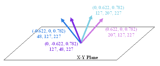
Figure 3: The figure shows four unit vectors that are separated from each other and a plane by approximately 45 degrees. The encoded RGB values for these vectors are included below the XYZ coordinates.
The second method uses four colors as well, but in this case we generate a dynamic 2x2 to contain them. The four normals are rotated to face the same direction as the eye-to-object vector, encoded, and placed in the texture in every frame. Because we rotate the vectors per-object, the results won't be quite as accurate as the per-vertex method. When we are close to large objects, some lines may disappear as the artist-line colors enter the same range as the edge-line colors. We sample the dynamic 2x2 texture using the pixel shader texreg2ar instruction. This instruction interprets the red and alpha values of a supplied texture as texture coordinates to sample a second texture. This essentially replaces four input colors from an artist-supplied texture with our four dynamic colors.
Our render texture now has the data needed to generate ink lines. Listing 4 shows the image-filter pixel program that does this. It compares opposite pixels, looking for differing colors and depth values. Ultimately, it depends on the one conditional instruction available in PS 1.1: cnd. This instruction will choose between two source colors and based on a single scalar. There are constant-supplied depth and edge thresholds that will specify the difference needed for RGB and alpha values to generate ink lines.
Listing 4
ps.1.1 ; inker pixel shader
def c0, 0.0f, 0.0f, 0.0f, 0.9f    ; threshold for normals
def c1, 0.0f, 0.0f, 0.0f, 0.25f   ; depth threshold
def c2, 1.0f, 1.0f, 1.0f, 0.0f    ; white and transparent
def c3, 0.0f, 0.0f, 0.0f, -0.25f  ; depth adjustment

tex t0
tex t1
tex t2
tex t3

dp3 r0.rgb, t0_bx2, t2_bx2  ; dot the normals for opposite pixels
+sub r0.a, t0.a, t2.a       ; find depth differences
dp3 r1.rgb, t1_bx2, t3_bx2  ; repeat for other set
+sub r1.a, t1.a, t3.a

mad t0.a, t0.a, c3.a, c0.a  ; scale the normal threshold with depth
                            ; uses first texture stage pixel

sub_x4_sat r0.rgb, r0, t0.a ; subtract the normal threshold and clamp
+mad r0.a, r0.a, r0.a, c1.a ; square the differences + add threshold
sub_x4_sat r1.rgb, r1, t0.a ; repeat for other set
+mad r1.a, r1.a, r1.a, c1.a

mul_x4_sat r0.rgb, r0, r1   ; combine the clamped normal values
+add r0.a, r0.a, r1.a       ; combine the differences

add r0.a, 1 - r0.b, r0.a    ; combine depth and normal values

cnd r0, r0.a, C_LINE_COLOR, c2 ; set pixel line color
We also scale the edge threshold with the depth value of one of the pixels. This solves an annoying problem of smooth sections of the model turning into lines in the distance. You may need to modify the edge threshold and depth adjustment values. Optimal values depend on resolution, far plane distance, and the general look of different models in your game.
It is common for games to use partially-transparent textures for objects like fences and leaves, where modeling features in geometry would increase the polygon count drastically. This will work with our inker as long as we include alpha values when we render the object into the overlay texture. The best method for this is to use 1-bit alpha and turn on alpha-testing. Zero alpha pixels will be discarded and lines will be drawn around areas that remain visible.
Our inker also supports different line widths by changing the size of the render texture. A texture that is twice the size of the back buffer creates nice thin lines, assuming the hardware can support render surfaces that large. Smaller textures can create thicker lines, but these lines tend to look more pixilated as they thicken.
A better approach for thickening lines is to render the overlay lines into a second render texture instead of the back-buffer. This second texture is overlaid again with a "dilating" pixel program. This method is quite fast for low-resolution output, but can be limited by fill-rate in high-resolution modes. Listing 5 contains two pixel programs that use slightly different algorithms to "dilate" the original ink lines. The first pixel program thickens the lines by outputting an ink line pixel if any of the four sampled pixels are ink line pixels. The second pixel program creates smoothed lines by linearly interpolating between the line-color and transparent depending on how many ink line pixels are sampled.
Listing 5
ps.1.1 ; dilation pixel shader
def c0, 0.0f, 0.0f, 0.0f, 0.25f   ; for 1/4 multiplication
def c1, 0.0f, 0.0f, 0.0f, -0.75f  ; for subtracting
def c2, 1.0f, 1.0f, 1.0f, 0.0f    ; white and transparent

tex t0
tex t1
tex t2
tex t3

mul r0.a, 1 - t0.a, c0.a        ; sum 1/4 of inverse samples
mad r0.a, 1 - t1.a, c0.a, r0.a  ; alpha of lines are 1.0 alpha
mad r0.a, 1 - t2.a, c0.a, r0.a
mad r0.a, 1 - t3.a, c0.a, r0.a

add_x4 r0.a, r0.a, c1.a         ; subtract .75 and mul * 4
                                ; only transparent pixels will
                                ; remain transparent
cnd r0, r0.a, c2, C_LINE_COLOR  ; conditionally choose between
                                ; transparent and line color

ps.1.1  ; smooth dilation pixel shader
def c0, 0.0f, 0.0f, 0.0f, 0.5f  ; smoothing threshold
                                ; 0.25 = max smoothing
                                ; 1.0 = no smoothing
def c2, 1.0f, 1.0f, 1.0f, 0.0f  ; white and transparent

tex t0
tex t1
tex t2
tex t3

mul r0.a, t0.a, c0.a        ; combine the four samples using
mad r0.a, t1.a, c0.a, r0.a  ; threshold and clamp
mad r0.a, t2.a, c0.a, r0.a
mad_sat r0.a, t3.a, c0.a, r0.a

mov r1.rgb, C_LINE_COLOR  ; create a zero alpha version
+ mov r1.a, c2            ; of line color

lrp r0, r0.a, C_LINE_COLOR, r1  ; interpolate line color

Speed and Quality
|
|