Putting It Together
Let's collate what we have learned and try to come up with all the require steps to do stencil shadow volumes before we tackle all the deficiencies of the techniques discussed. A general list of steps to implement stencil shadow volumes would be:
- Render all the objects using only ambient lighting and any other surface-shading attribute. Rendering should not depend on any particular light source. Make sure depth buffer is written.
- Starting with a light source, clear the stencil buffer and calculate the silhouette of all the occluders with respect to the light source.
- Extrude the silhouette away from the light source to a finite or infinite distance to form the shadow volumes and generate the capping if depth-fail technique was used. (Infinite shadow volume extrusion is not really compulsory)
- Render the shadow volumes using the selected technique. Depth-pass or depth-fail.
- Using the updated stencil buffer, do a lighting pass to shade (make it a tone darker) the fragments that corresponds to non-zero stencil values.
- Repeat step 2 to 5 for all the lights in the scene.
From the above list of steps, it should be quite obvious that having more lights means having more passes, which can burn a nice hole in your frame rate pocket. In fact, we have to be very selective when deciding which lights should be used for casting shadows. The article [4] has a nice discussion on selecting shadow casting lights within a scene lit by multiple light sources. Imagine your game character standing in the middle of a stadium with four gigantic batteries of floodlights shining down the field. There should be at least 4 shadows of you game character on the floor forming a cross due to the shadow casting from 4 different directions. Selecting only 1 light source here is going to make the scene look weird. Having multiple lights allows you to get nice realistic soft shadows but there are other ways to fake it without resorting to multiple light sources. Soft shadow is a huge topic and is not within the scope of this paper, so let's just drop it from here. Rule of thumb: Always select the dominant light sources in the scene. Using the viewing frustum to select light sources can be very dangerous, since you may have a nice giant 1000-mega watt photon busting spot light right behind the top of your head. It's not in your view frustum, but it's going to be responsible for the most distinct shadows you would see in the scene. Just remember, the fewer the number of lights, the more cycles and rendering passes you can save for other visually more important effects. So choose with care!
From the released screen shots of the upcoming Doom3 engine, I estimate that id Software would have to limit the number of shadow casting lights in any scene to a maximum of say 4 or 5. Well, we will know when Doom3 hits the shelves next year.
Silhouette Determination
The very first step to constructing a shadow volume is to determine the silhouette of the occluder. The stencil shadow algorithm requires that the occluders be closed triangle meshes. This meant that every edge in the model must only be shared by 2 triangles thus disallowing any holes that would expose the interior of the model. We are only interested in the edges shared by a triangle that faces the light source and another triangle that face away from the light source. There are many ways to calculate the silhouette edges and every single one of these methods are CPU cycles hungry. Lets assume we are working with an indexed triangle mesh.
Figure 10: Edge elimination for silhouette determination
Figure 10 shows one side of a box that is made up of four triangles with a consistent counter-clockwise winding. The broken lines indicate the redundant internal edges since we are only interested in the solid line that forms the outline of the box. The redundant internal edges are indexed twice as they are shared by two triangles. We take advantage of this property to come up with a simple method to determine the silhouette edges.
- Loop through all the model's triangles
- If triangle faces the light source (dot product > 0)
- Insert the three edges (pair of vertices), into an edge stack
- Check for previous occurrence of each edges or it's reverse in the stack
- If an edge or its reverse is found in the stack, remove both edges
- Start with new triangle
The above algorithm will ensure that the internal edges would be eventually removed from the stack since they are indexed by more than one triangle.
Eric Lengyel [11] presented another silhouette determination algorithm that makes use of the consistent winding (counterclockwise) of vertices. The method requires 2 passes on all the triangles of the model to filter in all the edges shared by pairs of triangles. The resultant edges list then undergo the dot product operations to get the edges that are shared by a light facing triangle and a non light facing triangle.
It is important to note that silhouette determination is one of the two most expensive operations in stencil shadow volume implementation. The other is the shadow volume rendering passes to update the stencil buffer. These two areas are prime candidates for aggressive optimizations, which we will discuss in detail at the concluding sections of this paper.
Generating Shadow Volume Capping
Remember that shadow volume capping is only necessary for the depth-fail technique. The purpose of doing shadow volume capping is to ensure that our shadow volume is closed, and it must be closed even at infinity. Interestingly, the extrusion of geometries for point light sources and infinite directional light sources are different. Point light sources would extrude the silhouette edges exactly point for point while infinite directional light sources would extrude all silhouette edges to a single point at infinity. This would meant that the shadow volume's back capping would be redundant for infinite directional light sources as it is already closed.
The ideal time to generate the front and back capping would be during the silhouette generation since we are already generating the angles between the light vector and the edges. For the front cap, we just need to duplicate all front facing geometries and use these geometries for extrusion to form the back capping as well. Note that the back cap is only necessary for point light sources.
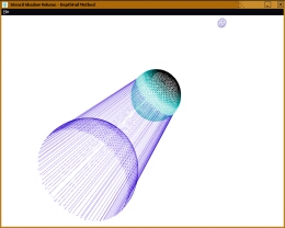
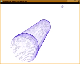
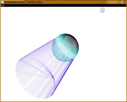
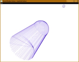
Figure 11: Closed shadow volume with point light source
Figure 11 shows two sets of images employing different geometries to close the shadow volume. The first row depicts a closed shadow volume formed by a front and back capping reusing light facing geometries. The second row shows a closed shadow volume with a front cap that reuses light facing geometries of the occluder and a triangle-fan back cap constructed from extruded silhouette edges. The triangle-fan back cap should be used as it results in less geometry and hence requires less memory and rendering time. When reusing the front facing geometries of the occluder, we should be extremely careful with regards to rendering the shadow volume since the shadow volume's front capping geometries are physically coplanar with the occluder's front facing geometries. Most often than not, precision problems will cause the front capping geometries of the shadow volume to be rendered in front of the occluder's front facing geometries causing the entire occluder to be engulfed in its own shadow volume. We can make use of the D3DRS_ZBIAS flag in Direct3D's D3DRENDERSTATETYPE to force the occluder's front facing geometries to be rendered in front of its shadow volume front cap. Simply use the D3DRS_ZBIAS flag when setting the render state (e.g. pd3dDevice->SetRenderState(D3DRS_ZBIAS, value)). We set the flag value to a higher value for the occluder's geometries and a lower value for its shadow volume. This will ensure that the front cap of the shadow volume is rendered behind the occluder's front facing geometries.

Extruding Geometries To Infinity
|