|
High Level View of Vertex Shader Programming
Only one vertex shader can be active at one time. It is a good idea to write vertex shaders on a per-task basis. The overhead for switching between different vertex shaders per-object is smaller than, for example, a texture change. So if an object needs a special form of transformation or lighting it will get the proper shader for this task. Let's look at an abstract example:
You are shipwrecked on a foreign planet and you move with your regular armor through the cellars which are illuminated by candlelight. A monster appears, and you crouch behind one of those crates one normally finds on other planets. While thinking about your destiny as a hero who saves worlds with jigsaws, you start counting the number of vertex shaders for this scene.
There is one for the monster to animate, light it and perhaps to reflect its environment. Other vertex shaders will be used for the floor, the walls, the crate, the camera, the candlelight and your jigsaw. Perhaps the floor, the walls, the jigsaw and the crate use the same shader, but the candlelight and the camera might use their own. It depends on your preference and the power of the underlying graphic hardware.
A vertex shader program will run through the following steps:
- check for vertex shader support by checking the D3DCAPS8::VertexShaderVersion field
- declaration of the vertex shader with the D3DVSD_* macros, to map vertex buffer streams to input registers
- setting the vertex shader constant registers with SetVertexShaderConstant()
- compiling an already written vertex shader with D3DXAssembleShader*() (Alternatives: could be pre-compiled using a Shader Assembler or it could be used in an effect file)
- creating a vertex shader handle with CreateVertexShader()
- setting a vertex shader with SetVertexShader() for a specific object
- delete a vertex shader with DeleteVertexShader()
Check for Vertex Shader Support
After declaring the vertex shader we would like to use, we have to check for the proper vertex shader support. It is important that you check the installed vertex shader software or hardware implementation of the end-user's PC. You are able to fall back on the fixed-function pipeline by doing this or you can suggest that they install the newest DirectX drivers with at least a software emulation of vertex shaders. The following statement in the Common Files framework function ConfirmDevice() will do that for you:
if( pCaps->VertexShaderVersion < D3DVS_VERSION(1,0) )
  return E_FAIL;
This one checks the D3DCAPS8 structure pCaps for vertex shader support. This structure is filled by routines of the Common Files framework when our game starts up.
Supported vertex shader versions are:
| Version |
Functionality |
| 0.0 |
DirectX 7 |
| 1.0 |
DirectX 8 without address register A0 |
| 1.1 |
DirectX 8 and DirectX 8.1 with one address register A0 |
| 2.0 |
DirectX 9 |
The only difference between the levels 1.0 and 1.1 is the support of the a0 register. The DirectX 8.0 and DirectX 8.1 reference rasterizer supports vertex shader version 1.1 in software. The software emulation delivered by Microsoft and written by Intel and AMD for their respective CPUs supports also version 1.1. The ATI RADEON supports no vertex shader (0.0) in hardware. Geforce3 and RADEON 8500-driven boards support version 1.1. As far as I know, no graphics card supports 1.0 at the moment, so it is a legacy version.
Vertex Shader Declaration
You have to declare a shader before using it. You might call this declaration a static external interface. An example might look like this:
float c[4] = {0.0f,0.5f,1.0f,2.0f};
DWORD dwDecl0[] = {
  D3DVSD_STREAM(0),
  D3DVSD_REG(0, D3DVSDT_FLOAT3 ),      // input register v0
  D3DVSD_REG(5, D3DVSDT_D3DCOLOR ),    // input Register v5
  D3DVSD_CONST(0,1),*(DWORD*)&c[0],*(DWORD*)&c[1],*(DWORD*)&c[2],*(DWORD*)&c[3],
  D3DVSD_END()
};
This vertex shader declaration sets data stream 0 with D3DVSD_STREAM(0). Later, SetStreamSource() binds a vertex buffer to a device data stream by using this declaration. You are able to feed different data streams to the Direct3D rendering engine this way.
For example, one vertex buffer could hold positions and normals, while a second holds color values and texture coordinates. This makes switching between single and multi texture rendering trivial: just don't enable the stream with the second set of texture coordinates.
You have to declare which input vertex properties or incoming vertex data has to be mapped to which input register. For example the position data could be processed by the input register 0 (v0) with D3DVSD_REG(0, D3DVSDT_FLOAT3 ) and the normal data could be processed by input register 3 (v3) with D3DVSD_REG(3, D3DVSDT_FLOAT3 ). How a developer maps each input vertex property to a specific input registers is not important except for one thing: he has to remember it later :-).
Mapping of the vertex input registers is fixed for the fixed-function pipeline, but not for a vertex shader. d3d8types.h holds a list of #defines to structurize the vertex input. These are the input registers used for the fixed-function pipeline. Therefore specific vertex elements such as position or normal must be placed in specified registers located in the vertex input memory. For example the position will be bound with D3DVSDE_POSITION to Register 0, the diffuse color will be bound with D3DVSDE_DIFFUSE to Register 5. Here's the whole list from d3d8types.h:
#define D3DVSDE_POSITION 0
#define D3DVSDE_BLENDWEIGHT 1
#define D3DVSDE_BLENDINDICES 2
#define D3DVSDE_NORMAL 3
#define D3DVSDE_PSIZE 4
#define D3DVSDE_DIFFUSE 5
#define D3DVSDE_SPECULAR 6
#define D3DVSDE_TEXCOORD0 7
#define D3DVSDE_TEXCOORD1 8
#define D3DVSDE_TEXCOORD2 9
#define D3DVSDE_TEXCOORD3 10
#define D3DVSDE_TEXCOORD4 11
#define D3DVSDE_TEXCOORD5 12
#define D3DVSDE_TEXCOORD6 13
#define D3DVSDE_TEXCOORD7 14
#define D3DVSDE_POSITION2 15
#define D3DVSDE_NORMAL2 16
D3DVSD_REG binds a single vertex register to a vertex element/property from the vertex stream. In our example a D3DVSDT_FLOAT3 value should be placed into the first input register and a D3DVSDT_D3DCOLOR color value should be placed in the sixth input register.
The second parameter of D3DVSD_REG specifies the dimensionality and arithmetic data type. The following values are defined in d3d8types.h:
// bit declarations for _Type fields
#define D3DVSDT_FLOAT1 0x00 // 1D float expanded to (value, 0., 0., 1.)
#define D3DVSDT_FLOAT2 0x01 // 2D float expanded to (value, value, 0., 1.)
#define D3DVSDT_FLOAT3 0x02 // 3D float expanded to (value, value, value, 1.)
#define D3DVSDT_FLOAT4 0x03 // 4D float

// 4D packed unsigned bytes mapped to 0. to 1. range
// Input is in D3DCOLOR format (ARGB) expanded to (R, G, B, A)
#define D3DVSDT_D3DCOLOR 0x04

#define D3DVSDT_UBYTE4 0x05 // 4D unsigned byte
// 2D signed short expanded to (value, value, 0., 1.)
#define D3DVSDT_SHORT2 0x06
#define D3DVSDT_SHORT4 0x07 // 4D signed short
D3DVSD_CONST loads the constant values into the vertex shader constant memory. The first parameter is the address of the constant array to begin filling data. Possible values range from 0 to 95. We start at 0. The second number is the number of constant vectors (quad-float) to load. One vector is 128 bit long, so we load four 32-bit FLOATs at once. D3DVSD_END generates an END token.
Another example:
float	c[4] = {0.0f,0.5f,1.0f,2.0f};
DWORD dwDecl[] = {
  D3DVSD_STREAM(0),
  D3DVSD_REG(0, D3DVSDT_FLOAT3 ), //input register v0
  D3DVSD_REG(3, D3DVSDT_FLOAT3 ), // input register v3
  D3DVSD_REG(5, D3DVSDT_D3DCOLOR ), // input register v5
  D3DVSD_REG(7, D3DVSDT_FLOAT2 ), // input register v7
  D3DVSD_CONST(0,1),*(DWORD*)&c[0],*(DWORD*)&c[1],*(DWORD*)&c[2],*(DWORD*)&c[3],
  D3DVSD_END()
};
Data stream 0 is set with D3DVSD_STREAM(0). The position values (value, value, value, 1.0) will be bound to v0, the normal values will be bound to v3, the diffuse color will be bound to v5 and one texture coordinate (value, value, 0.0, 1.0) will be bound to v7.
Setting the Vertex Shader Constant Registers
You will fill the vertex shader constant registers with SetVertexShaderConstant() and get the values from this registers with GetVertexShaderConstant(). In the Dolphin example of the DirectX 8 SDK this might look like:
// Set the vertex shader constants
m_pd3dDevice->SetVertexShaderConstant( 0, &vZero, 1 );
m_pd3dDevice->SetVertexShaderConstant( 1, &vOne, 1 );
m_pd3dDevice->SetVertexShaderConstant( 2, &vWeight, 1 );
m_pd3dDevice->SetVertexShaderConstant( 4, &matTranspose, 4 );
m_pd3dDevice->SetVertexShaderConstant( 8, &matCameraTranspose, 4 );
m_pd3dDevice->SetVertexShaderConstant( 12, &matViewTranspose, 4 );
m_pd3dDevice->SetVertexShaderConstant( 20, &fLight, 1 );
m_pd3dDevice->SetVertexShaderConstant( 21, &fDiffuse, 1 );
m_pd3dDevice->SetVertexShaderConstant( 22, &fAmbient, 1 );
m_pd3dDevice->SetVertexShaderConstant( 23, &fFog, 1 );
m_pd3dDevice->SetVertexShaderConstant( 24, &fCaustics, 1 );
m_pd3dDevice->SetVertexShaderConstant( 28, &matProjTranspose, 4 );
SetVertexShaderConstant() is declared as
HRESULT SetVertexShaderConstant(
  DWORD Register,
  CONST void* pConstantData,
  DWORD ConstantCount);
As you'll remember from above, there are at least 96 constant registers (MATROX G550: 256 constant registers; I didn't get any information about whether they are accessible by a vertex shader program), that could be filled with four floating-point values before the vertex shader is executed. The first parameter holds the register address at which to start loading data into the vertex constant array. The last parameter holds the number of constants (4 x 32-bit values) to load into the vertex constant array. So in the first row above, vZero will be loaded into register 0. matTranspose will be loaded into register 4, 5, 6, and 7. matViewTranspose will be loaded into 12, 13, 14, 15. The registers 16, 17, 18, 19 are not used. fLight is loaded into register 20. The registers 25, 26, 27 are not used.
So what's the difference between D3DVSD_CONST used in the vertex shader declaration and SetVertexShaderConstant()? The first one can be used one time, the second one before every DrawPrimitive*() call.
Ok, now we have learned how to check the supported version number of the vertex shader hardware, how to declare a vertex shader and how to set the constants in the constant registers of a vertex shader unit. The next thing to learn is how to write and compile a vertex shader program.
Writing and Compiling a Vertex Shader
Before we are able to compile a vertex shader, we have to write one (old wisdom :-) ). I would like to give you a high-level overview of the instruction set in the next lines and dive into the details of vertex shader programming in the next lesson named "Programming Vertex Shaders".
There are 17 different instructions:
| Instruction |
Parameters |
Action |
| add |
dest, src1, src2 |
add src1 to src2 (and the optional negation creates substraction) |
| dp3 |
dest, src1, src2 |
three-component dot product
dest.x = dest.y = dest.z = dest.w =
(src1.x * src2.x) + (src1.y * src2.y) + (src1.z * src2.z)
|
| dp4 |
dest, src1, src2 |
four-component dot product
dest.w = (src1.x * src2.x) + (src1.y * src2.y) + (src1.z * src2.z) + (src1.w * src2.w);
dest.x = dest.y = dest.z = unused
What is the difference between dp4 and mul? dp4 multiplies by scalar and mul by vector.
|
| dst |
dest, src1, src2 |
calculate distance vector
dest.x = 1;
dest.y = src1.y * src2.y
dest.z = src1.z
dest.w = src2.w
Useful for standard attenuation:
  // find the distance
  mov r0.xyz, v0.xyz         ; load vertex position
  dp3 r1.yz, r0.xyz, r0.xyz  ; put d*d in r1.y and r1.z
  rsq r2.y, r1.y             ; 1/d
  rcp r2.yw, r2.y            ; put d in r2.y and r2.w
dst r3, r1, r2 ; find the distance from v0 to origin |
| expp |
dest, src.w |
Exponential 10-bit precision
  float w = src.w;
  float v = (float)floor(src.w);

  dest.x = (float)pow(2, v);
  dest.y = w - v;

  // Reduced precision exponent
  float tmp = (float)pow(2, w);
  DWORD tmpd = *(DWORD*)&tmp & 0xffffff00;

  dest.z = *(float*)&tmpd;
  dest.w = 1;
Shortcut:
  dest.x = 2 **(int) src.w
  dest.y = mantissa(src.w)
  dest.z = expp(src.w)
dest.w = 1.0 |
| lit |
dest, src |
Calculates lighting coefficients from two dot products and a power.
src.x = N*L ; The dot product between normal and direction to light
src.y = N*H ; The dot product between normal and half vector
src.z = ignored ; This value is ignored
src.w = specular power ; The value must be between 128.0 and 128.0
usage:
  dp3 r0.x, rn, c[LIGHT_POSITION]
  dp3 r0.y, rn, c[LIGHT_HALF_ANGLE]
  mov r0.w, c[SPECULAR_POWER]
  lit r0, r0
Effect:
dest.x = 1.0;
dest.y = max (src.x, 0.0, 0.0);
dest.z= 0.0;
if (src.x > 0.0 && src.w == 0.0)
dest.z = 1.0;
else if (src.x > 0.0 && src.y > 0.0)
dest.z = (src.y)src.w
dest.w = 1.0;
|
| logp |
dest, src.w |
Logarithm 10-bit precision
float v = ABSF(src.w);
if (v != 0)
{
int p = (int)(*(DWORD*)&v >> 23) - 127;
dest.x = (float)p; // exponent
p = (*(DWORD*)&v & 0x7FFFFF) | 0x3f800000;
dest.y = *(float*)&p; // mantissa;
float tmp = (float)(log(v)/log(2));
DWORD tmpd = *(DWORD*)&tmp & 0xffffff00;
dest.z = *(float*)&tmpd;
dest.w = 1;
}
else
{
dest.x = MINUS_MAX();
dest.y = 1.0f;
dest.z = MINUS_MAX();
dest.w = 1.0f;
}
Shortcut:
dest.x = exponent((int)src.w)
dest.y = mantissa(src.w)
dest.z = log2(src.w)
dest.w = 1.0
|
| mad |
dest, src1, src2, src3 |
dest = (src1 * src2) + src3 |
| max |
dest, src1, src2 |
dest = (src1 >= src2)?src1:src2 |
| min |
dest, src1, src2 |
dest = (src1 < src2)?src1:src2 |
| mov |
dest, src |
move
Optimization tip: question every use of mov (try to rap that!), because there might be methods with more functionality in one instruction
|
| mul |
dest, src1, src2 |
set dest to the product of src1 and src2
  ;Cross Product (r5 = r7 X r8), r0 used as a temp
  mul r0,-r7.zxyw,r8.yzxw
mad r5,-r7.yzxw,r8.zxyw,-r0 |
| nop |
|
do nothing |
| rcp |
dest, src.w |
  if(src.w == 1.0f)
  {
    dest.x = dest.y = dest.z = dest.w = 1.0f;
  }
  else if(src.w == 0)
  {
    dest.x = dest.y = dest.z = dest.w = PLUS_INFINITY();
  }
  else
  {
    dest.x = dest.y = dest.z = m_dest.w = 1.0f/src.w;
  }
Division:
  ; scalar r0.x = r1.x/r2.x
  RCP r0.x, r2.x
MUL r0.x, r1.x, r0.x |
| rsq |
dest, src |
reciprocal square root of src (much more useful than straight 'square root'):
  float v = ABSF(src.w);
  if(v == 1.0f)
  {
    dest.x = dest.y = dest.z = dest.w = 1.0f;
  }
  else if(v == 0)
  {
    dest.x = dest.y = dest.z = dest.w = PLUS_INFINITY();
  }
  else
  {
    v = (float)(1.0f / sqrt(v));
    dest.x = dest.y = dest.z = dest.w = v;
  }
Square root:
  ; scalar r0.x = sqrt(r1.x)
  RSQ r0.x, r1.x
MUL r0.x, r0.x, r1.x |
| sge |
dest, src1, src2 |
dest = (src1 >=src2) ? 1 : 0 |
| slt |
dest, src1, src2 |
dest = (src1 < src2) ? 1 : 0 |
You might pin this list to your pinboard or your monitor. Check out the SDK for additional information.
The Vertex Shader ALU is a multi-threaded vector processor operation on quad-float data. It consists of two functional units. The SIMD Vector Unit is responsible for the mov, mul, add, mad, dp3, dp4, dst, min, max, slt and sge instructions. The Special Function Unit is responsible for the rcp, rsq, log, exp and lit instructions. Most of these instructions take one cycle to execute; rcp and rsq take more than one cycle under specific circumstances. I guess there is a synchronisation problem between the two units of the ALU with rcp and rsq, because I read several times that the results of these two instructions shouldn't be used immediately.
rsq is mainly used in normalizing vectors to be used in lighting equations. The exponential instruction expp can be used for fog effects, procedural noise generation (see nVidia Perlin Noise example), behavior of particles in a particle system (see nVidia Particle System example) or to implement a system for how objects in a game are damaged. You will use it in any case when a fast changing function is necessary. This is contrary of the use of logarithm functions with logp, that are useful if an extremely slow growing function is necessary (also they grow at the beginning pretty fast). A log function can be the inverse of a exponential function, meaning it undoes the operation of the exponential function.
The lit instruction deals by default with directional lights. It calculates the ambient, diffuse & specular factors with clamping based on N * L and N * H and the specular power. So there is no attenuation involved. But you can use an attenuation level separately with the result of lit by using the dst instruction. dst assists in constructing attentuation factors for point and spot lights.
The min and max instructions allow for clamping and absolute value computation.
There are also macros that are supported by the vertex shader assemblers. You should think about using macros carefully. If you use them, you might loose control over your 128-instruction limit and possible optimization path. On the other side the software emulation mode provided by Intel or by AMD for their processors is able to optimize a m4x4 macro and perhaps others now or in the future. So if you need four dp4 calls in your vertex shader assembly source, it might be a good idea to replace them by m4x4:
| Macro |
Parameters |
Action |
Clocks |
| expp |
dest, src1 |
provides exponential with full precision to at least 1/220 |
12 |
| frc |
dest, src1 |
returns fractional portion of each input component |
3 |
| log |
dest, src1 |
provides log2(x) with full float precision of at least 1/220 |
12 |
| m3x2 |
dest, src1, src2 |
computes the product of the input vector and a 3x2 matrix |
2 |
| m3x3 |
dest, src1, src2 |
computes the product of the input vector and a 3x3 matrix |
3 |
| m3x4 |
dest, src1, src2 |
computes the product of the input vector and a 3x4 matrix |
4 |
| m4x3 |
dest, src1, src2 |
computes the product of the input vector and a 4x3 matrix |
3 |
| m4x4 |
dest, src1, src2 |
computes the product of the input vector and a 4x4 matrix |
4 |
We have learned that in vs.1.1 there are 16 input registers, 96 constant registers, 12 temporary registers, at least 1 address register and 13 output registers per rasterizer. Each one might be able to handle 4x32-bit values. Each 32-bit value is accessible by x, y, z and w. So a 128-bit value consists of a x, y, z and w value, each 32 bits long. The syntax for every instruction in this table is
OpName dest, [-]s1 [,[-]s2 [,[-]s3]] ;comment
e.g.:
mov r1, r2
mad r1, r2, r3, r4
Using the Input Registers
The 16 input vertex registers can be accessed by using their names v0 to v15. The four parts of a input vertex register can be accessed via v0.x, v0.y, v0.z or v0.w. Typical values provided to the input vertex registers are:
- Position(x,y,z,w)
- Diffuse color (r,g,b,a) -> 0.0 to +1.0
- Specular color (r,g,b,a) -> 0.0 to +1.0
- Up to 8 Texture coordinates (each as s, t, r, q) but normally 4 or 6, one for each physical hardware texture unit
- Fog (f,*,*,*) -> value used in fog equation
- Point size (p,*,*,*)
You can access the x-value of the position with v0.x, the y-value with v0.y and so on. If you would like to know the green component of the diffuse color, you check v1.y. If you use 4 textures, because you have hardware that supports that many at once, you are able to check the fog value with v7.x. The other three 32-bit values, v7.y, v7.z and v7.w, are not used. The input vertex registers are read-only. A single instruction may access only one vertex input register. Unspecified components of the input register default to 0.0 for the second (e.g. v1.y) and third (e.g. v1.z) component and to 1.0 for the fourth component (e.g. v1.w). In the following example the four-component dot product from c7 and v0 is moved into oPos.w and the material color in v5 is moved into the output register oD0 for the diffuse color.
dp4 oPos.w , v0 , c7 ; emit projected w position
mov oD0 , v5 ; material color
The data in an input register remains persistant throughout the vertex shader execution. That means they retain their data longer than the life-time of a vertex shader. So it might be possible to re-use the data of the input registers in the next vertex shader.
Using the Constant Registers
Typical use of the constant registers are:
- Matrix data: quad-floats are typically one row of a 4x4 matrix
- Light characteristics (position, attenuation etc)
- Current time
- Vertex interpolation data
- Procedural data
The constant registers are read-only from the perspective of the vertex shader. You can use only one constant register per instruction, but you can use it several times. Normally you access a constant register like this:
mul r5, c11, c11 ; The product of c11 and c11 is stored in r5
Reads from out-of-range constant registers return (0.0, 0.0, 0.0, 0.0). There are 96 quad-floats to store constant data to allow a reasonably large set of matrices for indexed skinning. It looks like Matrox has hightened this number to 256 in their G550 to allow facial expression animation.
Using the Address Register
You access the address registers with a0 to an (more than one address register should be available in vertex shader versions higher than 1.1). The only use of a0 in vs 1.1 is as an indirect addressing operator to offset constant memory.
c[a0.x + n] ; supported only in version 1.1 and higher
a0.x is the only valid component of a0. A vertex shader may write a0.x only via the mov instruction.
Beware of a0.x if there is only a software emulation mode: it slows down.
So the 96 constant registers are accessible by c[n] (absolute) or relative with c[a0.x + n].
Using the Temporary Registers
To get access to the 12 temporary registers you use r0 to r11. A few examples:
dp3 r2, r1, -c4 ; A three-component dot product: dest.x = dest.y = dest.z
                ; dest.w = (r1.x * -c4.x) + (r1.y * -c4.y) + (r1.z * -c4.z)
...
mov r0.x, v0.x
mov r0.y, c4.w
mov r0.z, v0.y
mov r0.w, c4.w
Each temporary register has single write and triple read access. Therefore an instruction could have the same temporary register three times as a source. Vertex shaders can not read a value from a temporary register before writing to it. If you try to read a temporary register that was not filled with a value, the API will give you an error message while creating the vertex shader (== CreateVertexShader()).
Using the Output Registers
The up to 13 write-only output registers might be accessed with the following register names. They are defined as the inputs of the rasterizer and preceded by a lower case 'o'. The output registers are named to suggest their use, when using pixel shaders.
| Name |
Value |
Description |
| oDn |
2 quad-floats |
Output color data directly to the pixel shader. Required for diffuse color (oD0) and specular color (oD1). |
| oPos |
1 quad-float |
Output position in homogenous clipping space. Must be written by the vertex shader. |
| oTn |
up to 8 quad-floats
Geforce 3: 4
RADEON 8500: 6
|
Output texture coordinates. Required for maximum number of textures simultaneously bound to the texture blending stage. |
| oPts.x |
1 scalar float |
Output point-size registers. Only the scalar x-component of the point size is functional |
| oFog.x |
1 scalar float |
the fog factor to be interpolated and then routed to the fog table. Only the first component is functional. |
dp4 oPos.x , v0 , c4 ; emit projected x position
dp4 oPos.y , v0 , c5 ; emit projected y position
dp4 oPos.z , v0 , c6 ; emit projected z position
dp4 oPos.w , v0 , c7 ; emit projected w position
mov oD0 , v5
mov oT0, v2 ; outputs the texture coordinates to oT0 from input register v2
Having a fog distance value permits more general fog effects then using the position's z or w values. It is interpolated before use as a distance in the standard fog equations used later in the pipeline.
Every vertex shader must write at least to one component of oPos or you will get an error message by the assembler.
When using vertex shaders the D3DTSS_TCI_* flags of D3DTSS_TEXCOORDINDEX are ignored. All texture coordinates are mapped in numerical order.
Optimization tip: emit to oPos as early as possible. Reorder instructions to make this happen.
When using vertex shaders with an implementation without pixel shaders (Direct3D 6 or 7), only the following output registers are available:
| Name |
Value |
Description |
| oDn |
2 quad-floats |
Output color data directly to the pixel shader. Required for diffuse color and specular color. |
| oPos |
1 quad-float |
Output position in homogenous clipping space. |
| oTn |
2 quad-floats |
Output texture coordinates. Required for maximum number of textures simultanously bound to the texture blending stage. |
All iterated values transferred out of the vertex shader are clamped to [0..1]. If you need signed values in the pixel shader, you must bias them in the vertex shader, and then re-expand them in the pixel shader by using _bx2.
Swizzling (only source registers: vn, cn, rn)
Swizzling is very useful for doing things cross products efficiently, where the source registers need to be rotated. Another use is converting constants such as (0.5, 0.0, 1.0, 0.6) into others such as (0.0, 0.0, 1.0, 0.0) or (0.6, 1.0, -0.5, 0.6).
All registers that are used in instructions as source registers can be swizzled. For example
MOV R1, R2.wxyz;
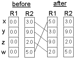
The destination register is R1. Source Registers are R2 or R3. They are located on the right side of the destination register. The instruction copies the R2.x into R1.w and R2.y into R1.z etc. All source registers can also be negated and swizzled:
MOV R1, -R2.xyyz
This works for all registers (temporary-, constant- and input-registers) that are used as a source in an instruction.
Masking (only destination registers: on, rn)
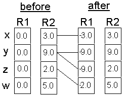
A destination register can mask which components are written to it. If you use R1, all the components are written from R2 to R1. If you choose for example
MOV R1.x, R2
only the x component is written to R1, whereas
MOV R1.xw, R2
writes only the x and w components of R2 to R1. No swizzling or negation is supported on the destination registers.
To summarize swizzling and masking:
| Component Modifier |
Description |
| r.[x][y][z][w] |
Destination mask |
| r.xwzy (for example) |
Source swizzle |
| -r |
Source negation |
Since any source can be negated, there is no need for a subtract instruction.
Here is a summariy on the available register types (available in vs 1.1 hardware) with i/o access privileges:
- Input: RO1 - 16 registers
- Temp: R1W3 - 12 registers
- Const: RO1 - 96 registers + one offset register: RW1
- Output: WO - by vertex properties
So far the biggest restrictions for a vertex shader could be summarized as:
- it must write to at least one component of the output register oPos
- 128 instruction limit
- every instruction may source no more than one constant register
- every instruction may source no more than one input register
Compiling a Vertex Shader
Direct3D uses byte-codes, whereas OpenGL parses a string. Because of this, the developer needs to assemble the vertex shader source with an assembler. This might help you finding bugs earlier in your development cycle and reduces load-time.
I see three different ways to compile a vertex shader:
- Write the vertex shader source into a separate ASCII file (e.g. test.vsh) and compile it with a vertex shader assembler into a binary file (e.g. test.vso). This file will be opened and read through the start up of your game. This way, not every person is able to read and modify your vertex shader source and the startup phase of your game is shortened.
- Write the vertex shader source into a separate ASCII file or as a char string into your *.cpp file and compile it "on the fly" while the app starts up with the D3DXAssembleShader*() functions.
- Write the vertex shader source in an effects file and open this effect file when the app starts up. The vertex shader will be compiled by reading the effect file with D3DXCreateEffectFromFile(). It is also possible to pre-compile an effects file. This way most of the handling of vertex shaders is simplified and handled by the effect file functions.
I will show you the three different ways in specific examples in the next lesson. So hold on ...
After we are able check the vertex shader support with the D3DCAPS8::VertexShaderVersion field, declare a vertex shader with the D3DVSD_* macros, set the constant registers with SetVertexShaderConstant() and at least have an idea how to write a vertex shader and how to compile it, we have to get a handle for the vertex shader by creating one.
Creating a Vertex Shader
The CreateVertexShader() function is used to create and validate a vertex shader:
HRESULT CreateVertexShader(
  CONST DWORD* pDeclaration,
  CONST DWORD* pFunction,
  DWORD* pHandle,
  DWORD Usage);
This function takes the vertex shader declaration, which maps vertex buffer streams to different vertex input registers in pDeclaration as a pointer and returns the shader handle in pHandle. The second parameter pFunction gets the vertex shader instructions compiled by D3DXAssembleShader()/ D3DXAssembleShaderFromFile() or the binary code pre-compiled by a vertex shader assembler. In the fourth parameter you can force software vertex processing with D3DUSAGE_SOFTWAREPROCESSING. This value must be used when the D3DRS_SOFTWAREVERTEXPROCESSING member of the D3DRENDERSTATETYPE enumerated type is TRUE, and it must be removed for vertex shaders when this flag is FALSE.
Setting a Vertex Shader
You set a vertex shader for a specific object by using SetVertexShader() before the DrawPrimitive*() call for that object. So this function dynamically loads the vertex shader between the primitive calls.
// set the vertex shader
m_pd3dDevice->SetVertexShader( m_dwVertexShader );
The only parameter you have to provide is the handle of the vertex shader created by CreateVertexShader().
The overhead of this call is lower than a SetTexture() call, so you
are able to use it often.
Vertex shaders are executed with SetVertexShader() as often as there are vertices. So if you try to visualize a rotating quad with four vertices, you will see in the nVidia Shader Debugger that the vertex shader runs four times, before the DrawPrimitive*() function is called.
Deleting a Vertex Shader
When your game shuts down, the resources for the vertex shader have to be freed. This must be done by calling DeleteVertexShader() with the vertex shader handle:
// delete the vertex shader
if (m_pd3dDevice->m_dwVertexShader != 0xffffffff)
{
  m_pd3dDevice->DeleteVertexShader( m_dwVertexShader );
  m_pd3dDevice->m_dwVertexShader = 0xffffffff;
}
Ok, now that we've walked step by step through a vertex shader creation process on a high level, let's summarize what you have learned so far:
- To use vertex shaders, you should check the vertex shader support of the software or hardware vertex shader implementation installed on the computer of your end-user with the D3DCAPS8::VertexShaderVersion field.
- You have to declare which input vertex properties or incoming vertex data has to be mapped to which input register. This mapping is done with the D3DVSD_* macros. You are able to fill the constant registers of the vertex shader with values by using the macros mentioned before or by using the SetVertexShaderConstant() function.
- After you have prepared everything this way and you have written a vertex shader, you are able to compile it (in at least three different ways), retrieve a handle to it by calling CreateVertexShader(), and setting it for execution by using SetVertexShader().
- To free up the resources that are allocated by the vertex shader you should call DeleteVertexShader() at the end of your game.

Next : Conclusion
|